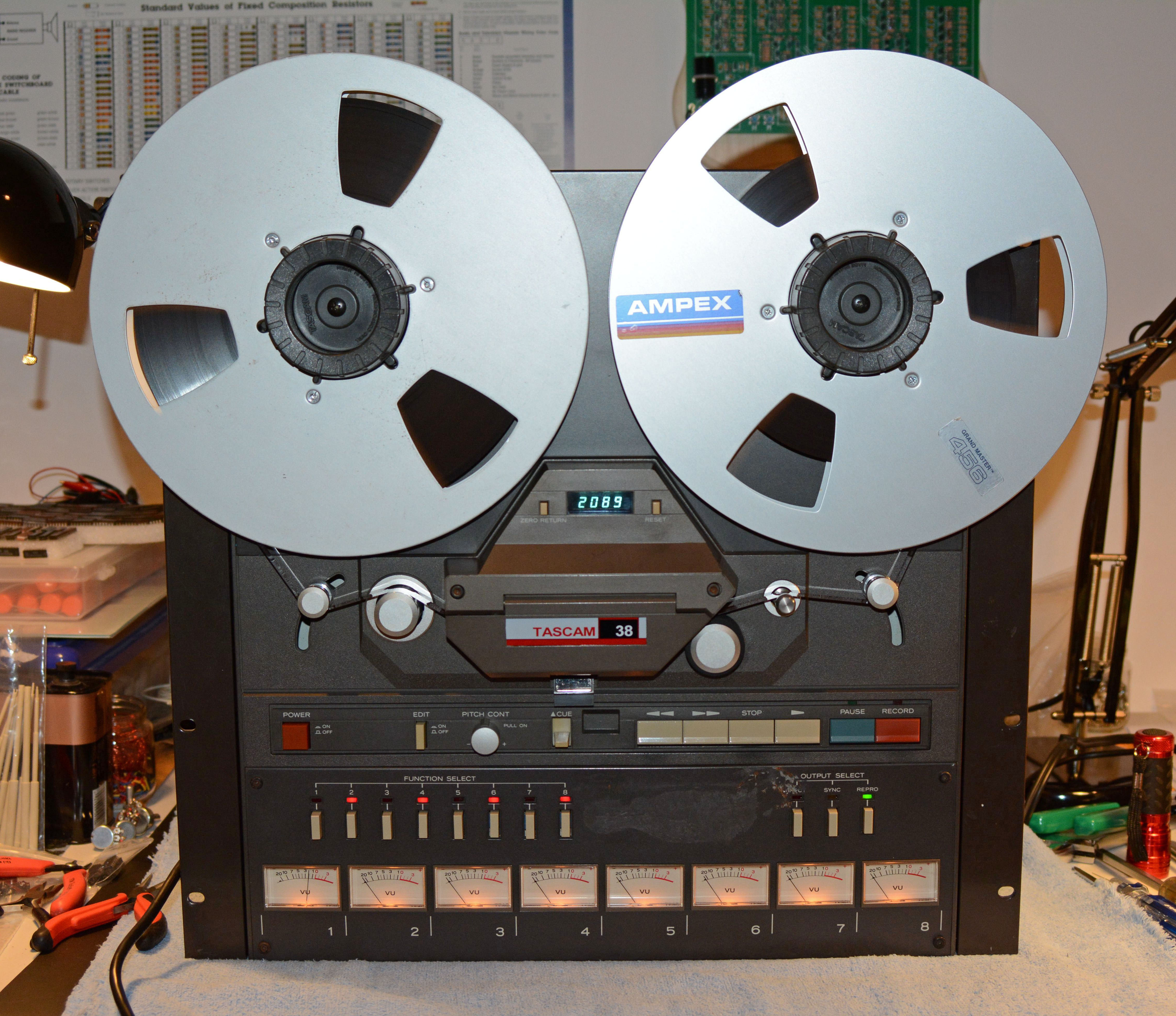
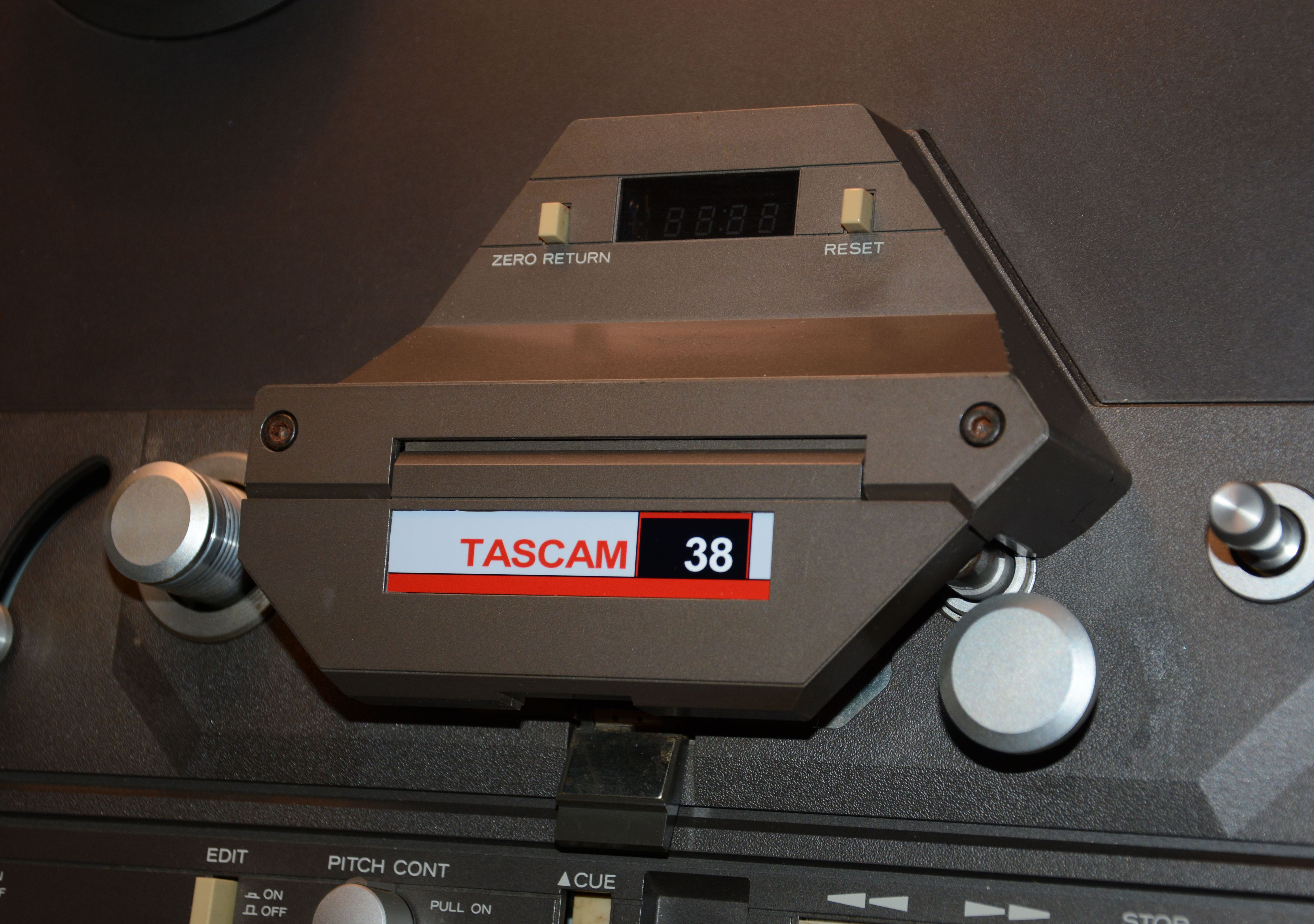
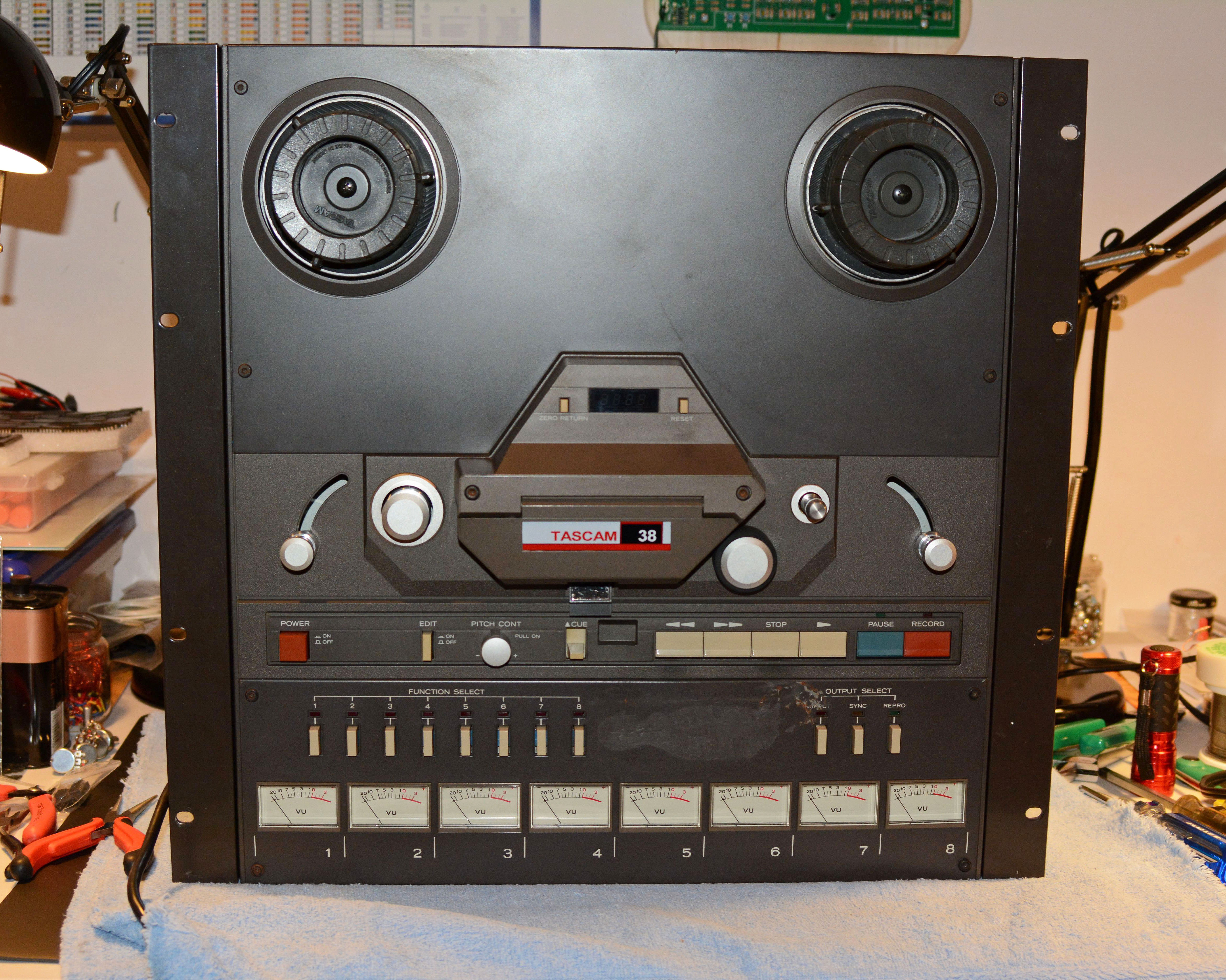
Tascam 38Reel-to-reel Tape Machine
Introduced in 1983 along with the models 32 and 34, the Tascam 38 was offered as a relatively low-cost 8-track tape recorder, intended for semi-professional use (i.e. serious musicians and low-budget studios). It uses 1/2" tape on up to 10.5" diameter reels, features three heads, and three brushed DC motors. Each channel has its own lighted VU meter and "Function Select" / record enable button. A "Cue" lever allows the tape lifters to be disengaged, allowing the output from the heads to be heard at all times, thus enabling locations on tape to be found during editing. Three "Output Select" buttons allow switching the selected output between the input, sync head, and repro head. On the back, a 12-pin WAKA remote connector allows a remote control to be attached, such as a Tascam RC-71, and a 1/4" jack allows a punch in/out pedal to be used, such as a Tascam RC-30P. Since this is a common model with plenty of good info elsewhere online, this article will focus on the repairs necessary to bring my unit back to good working order. I will also say briefly that it is an inferior machine to my Tascam 58; the transport is sloppier and less robust, the cue/edit function is cruder, the counter counts nonstandard lengths of time instead of seconds, the build is lighter and with more plastic, etc. However, it is still capable of excellent recordings, and is built with quality components and with a high degree of repairability scarcely found in modern equipment. Features
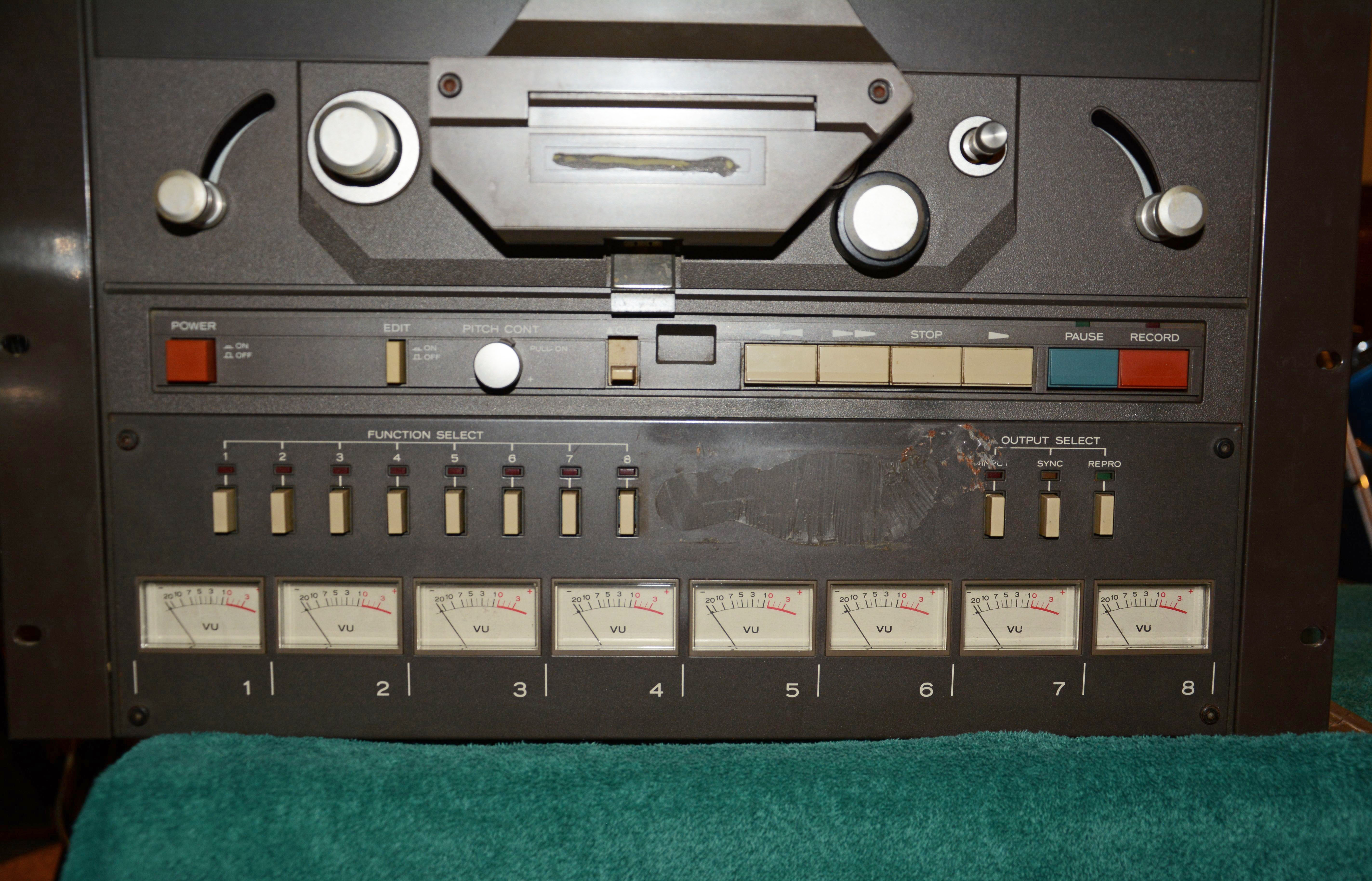
RepairsThis example of a Tascam 38 was purchased inexpensively along with a Tascam 32, its two-track equivalent. Both machines were very heavily used by a local low-budget studio in the '80s and '90s, followed by years in a slightly damp storage locker until the studio owner's death in February 2016. Needless to say, this machine was not in great condition when I received it in March 2016. Besides cosmetic issues (such as a thick coating of smoke residue, leftover silicone sealant used for splicing block attachment, no nameplate, etc.), both the pinch roller and the capstan belt had turned to goo, the capstan was glazed and covered with rusty patches, all but two VU meter lamps were burned out, channel 4 had no output, channels 1 and 3 had no signal in repro mode, the FF/REW functions were extremely sluggish, among other small faults. Here are some pictures of the machine's initial condition...
... and here is the list of repairs done to bring it back to good working order:
Some of these repairs are worthy of further explanation, so I will describe them below. Firstly, the main cosmetic fix on the machine: making a replacement for the missing plastic nameplate. These are often missing, due to the plastic warping outwards and the glue becoming brittle and cracking, and the fact that many owners dispose of them once they fall off. My solution was to print a copy of the original design on glossy photo paper with an inkjet printer, cut it to fit the spot, and glue it in with some PVC-E glue. A nice printable version of the design had conveniently already been made by Mike Zee of MZE-Electroarts Entertainment (see Links), but his solution of cutting a plastic piece and securing it with screws was not as appealing to me as gluing. Anyway, the result is shown below, which I'd say looks pretty good:
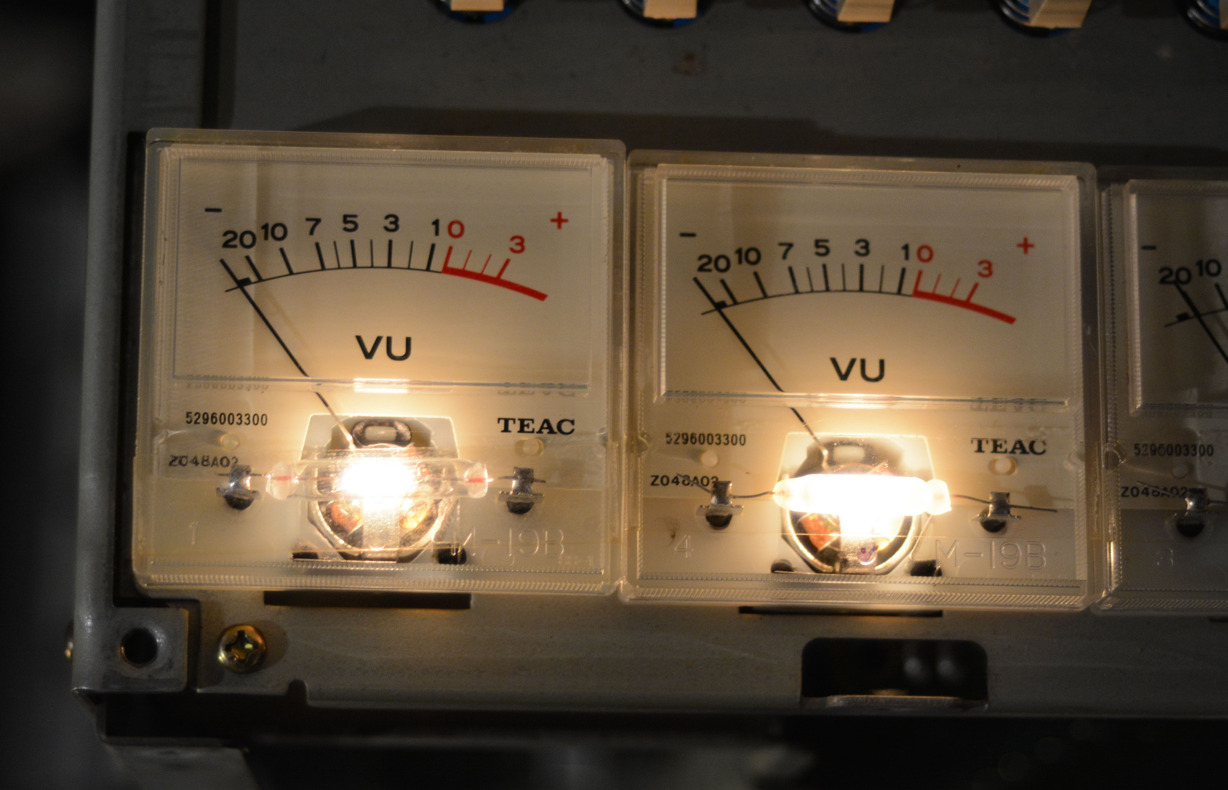
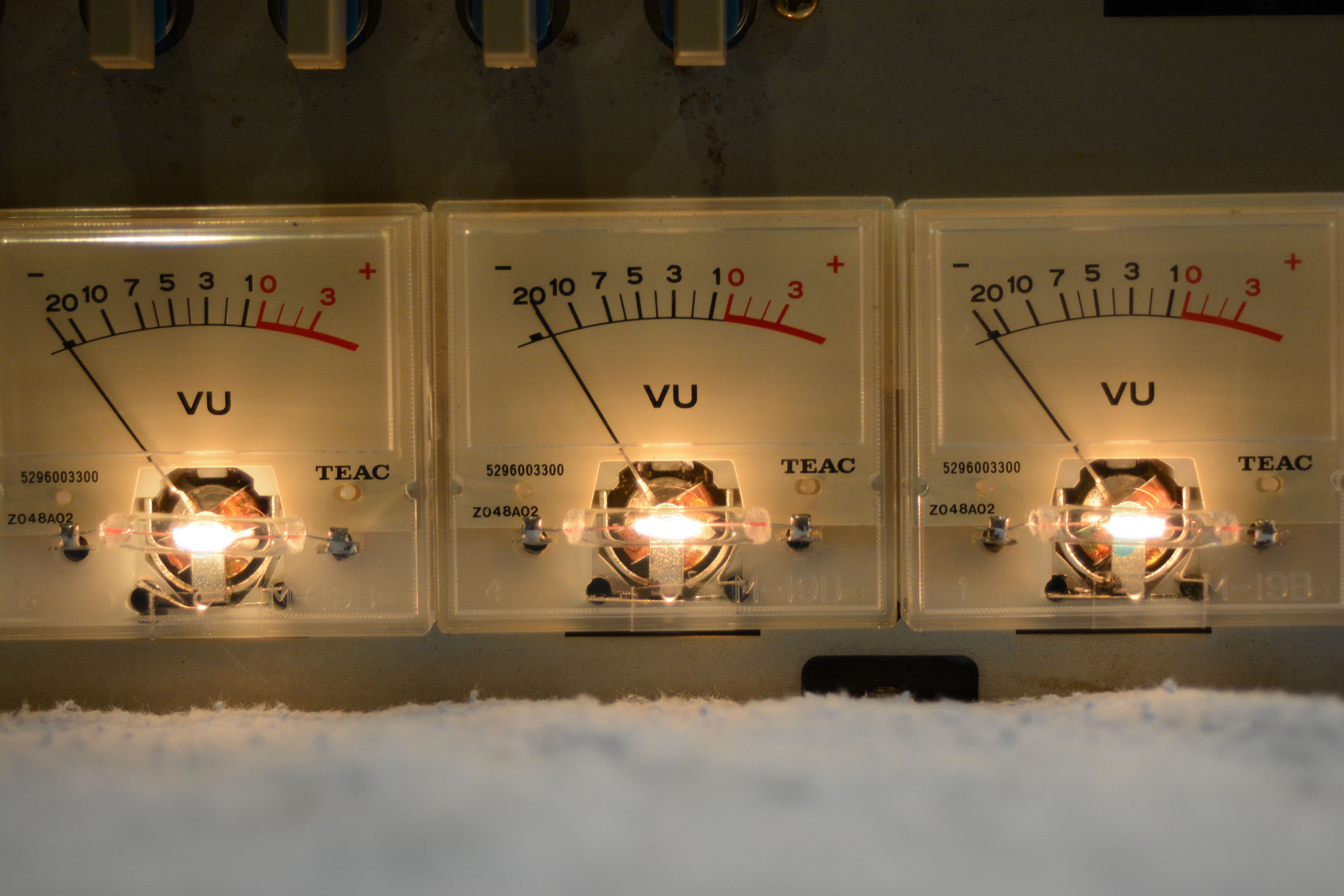
Another repair, both cosmetic and functional, was replacing the burned-out VU meter lamps. For these, type DA513 lamps from the supplier JKL were used (see Links), which are rated for 55mA at 8V; with the actual lamp supply of 6V AC, the current is somewhat lower. Although slightly larger than the originals and clear instead of frosted, they look great, with an almost identical illumination pattern. I replaced all of the original lamps, including the two non-defective but probably nearly-expired ones, for consistency and to avoid having to replace any more in the near future. In the leftmost picture below, an original and new lamp are shown side-by-side, with the original on the right. The other two pictures show all new lamps.
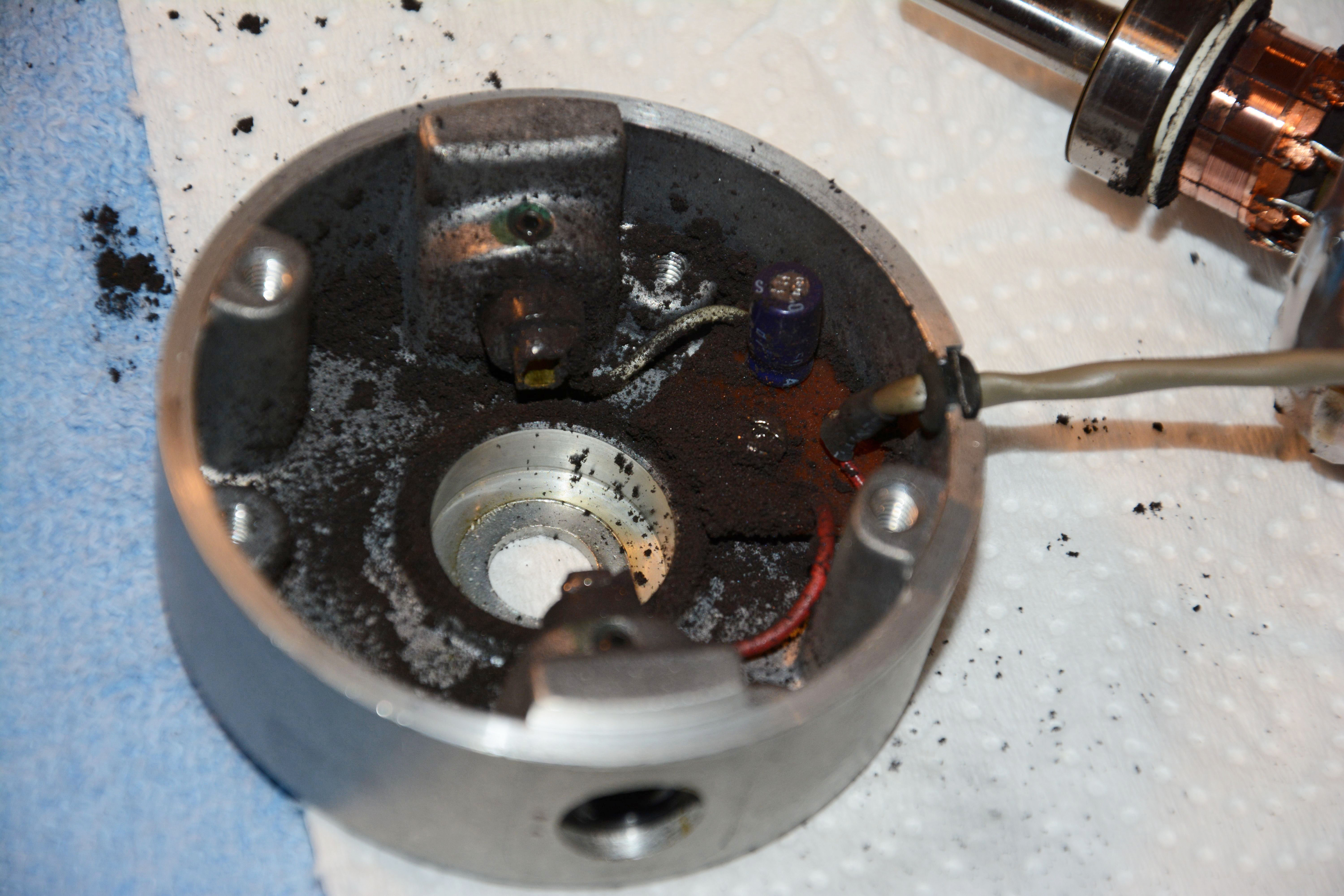
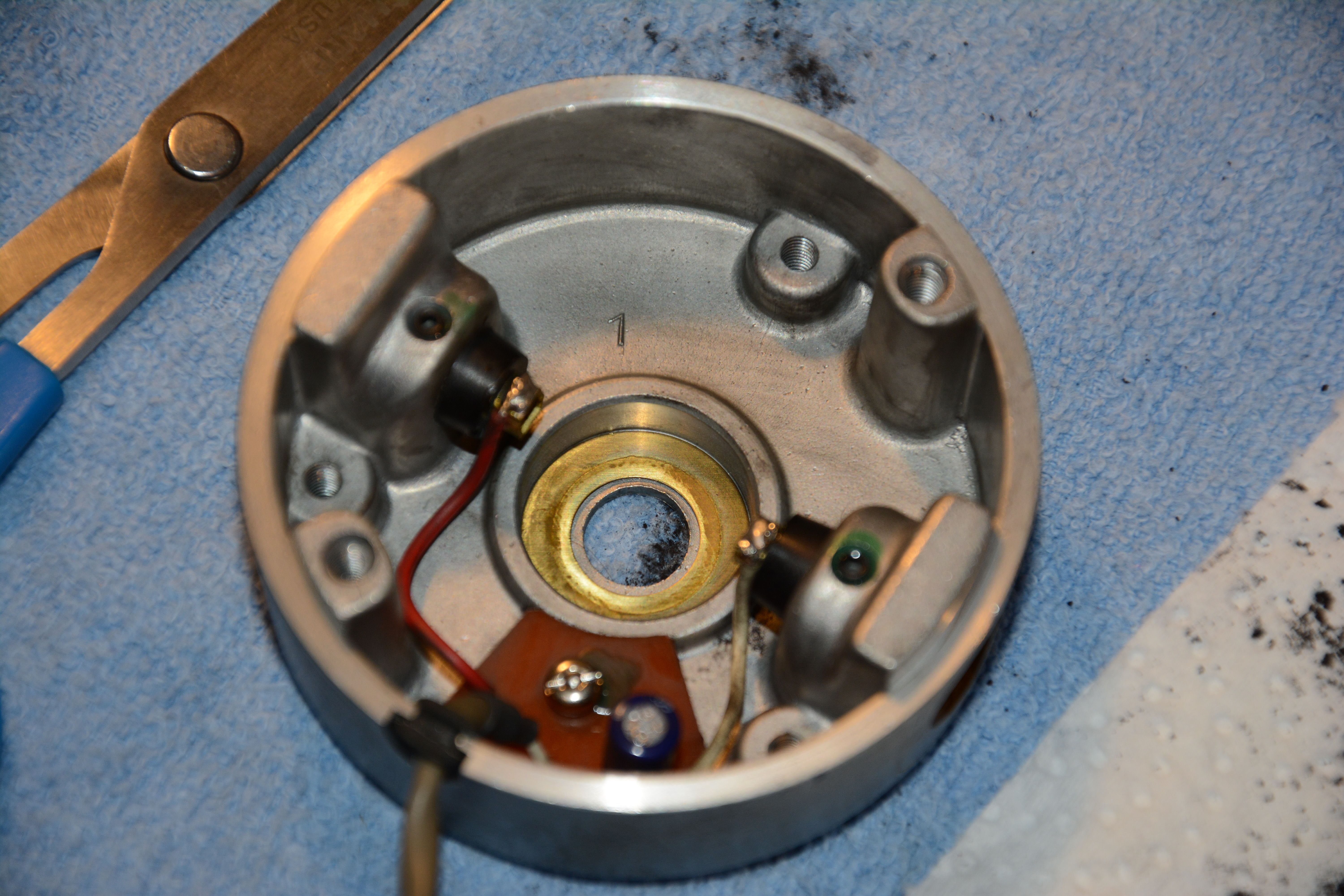
When performing this lamp replacement, the VU meters must be pulled off of their mounting tape (double-sided foam tape that had decomposed), and the horizontal strips of clear tape holding the meter lenses have to be removed in order to allow the lenses to hinge upward. On each meter, I replaced these horizontal tape strips with new vertical pieces holding the lenses in place, so that they can be easily detached without having to remove the meters from their foam mounting tape again. I also replaced the mounting tape; for this, I used new Duck brand 3/4" wide foam tape— wider than necessary, but usable. When sticking the VU meters to this foam tape, I found it was necessary to use the front panel to hold the meters in proper position as they touched it, which necessitated that the meter lenses were placed in their rectangular holes and held from the front with some temporary tape as the front panel was moved into normal position. If you just attach the meters haphazardly, the meter lenses will never fit properly in the holes on the front panel. Refurbishment of the reel motors was necessary to fix the sluggish Fast-Forward and Rewind modes. These brushed DC motors accumulate shaved-off carbon brush material (which is conductive) between sections of the commutator, resulting in poorer performance due to improper energization of the rotor coils. The removal of the motors from their mounting is the trickiest part of the process, due to the way the back mounting bracket is designed. Desoldering the motor from the control PCB is necessary. Once the motors are out, the refurbishment involves removing the brushes, disassembling them carefully, cleaning out the carbon powder (especially from between commutator sections), relubricating the bearings, and then putting everything back together. There is a good online tutorial about this process, which I've included in the Links section. Just remember to keep track of the orientation of the brushes when removing them, as well as the way the motor sections fit together. Here are some pictures, showing the remarkable amount of carbon shavings near the brushes, and the result of cleaning both the case and the commutator.
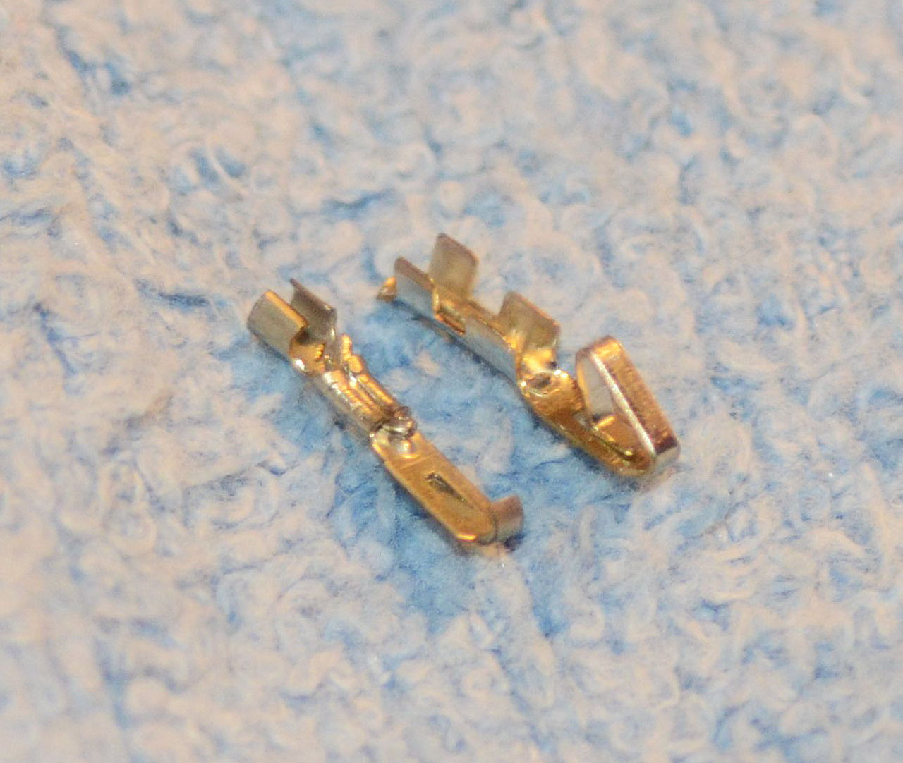
Another worthwhile fix to mention is that of the dead channel 4 output. I had this type of problem on both this unit and the 32, and the cause was the same: a broken pin on one of the female 0.1" Molex connectors from the motherboard to the output jacks. You can easily tell this, once the connector is removed, by holding a light behind it and looking into the holes; a bad pin will allow light to pass through, and the broken metal piece will move around inside. It's easy to fix this, simply by cutting and stripping the wire to the broken pin, securing a new pin to the wire (I already had some spares), and installing it into the connector. Here's the broken pin alongside its replacement:
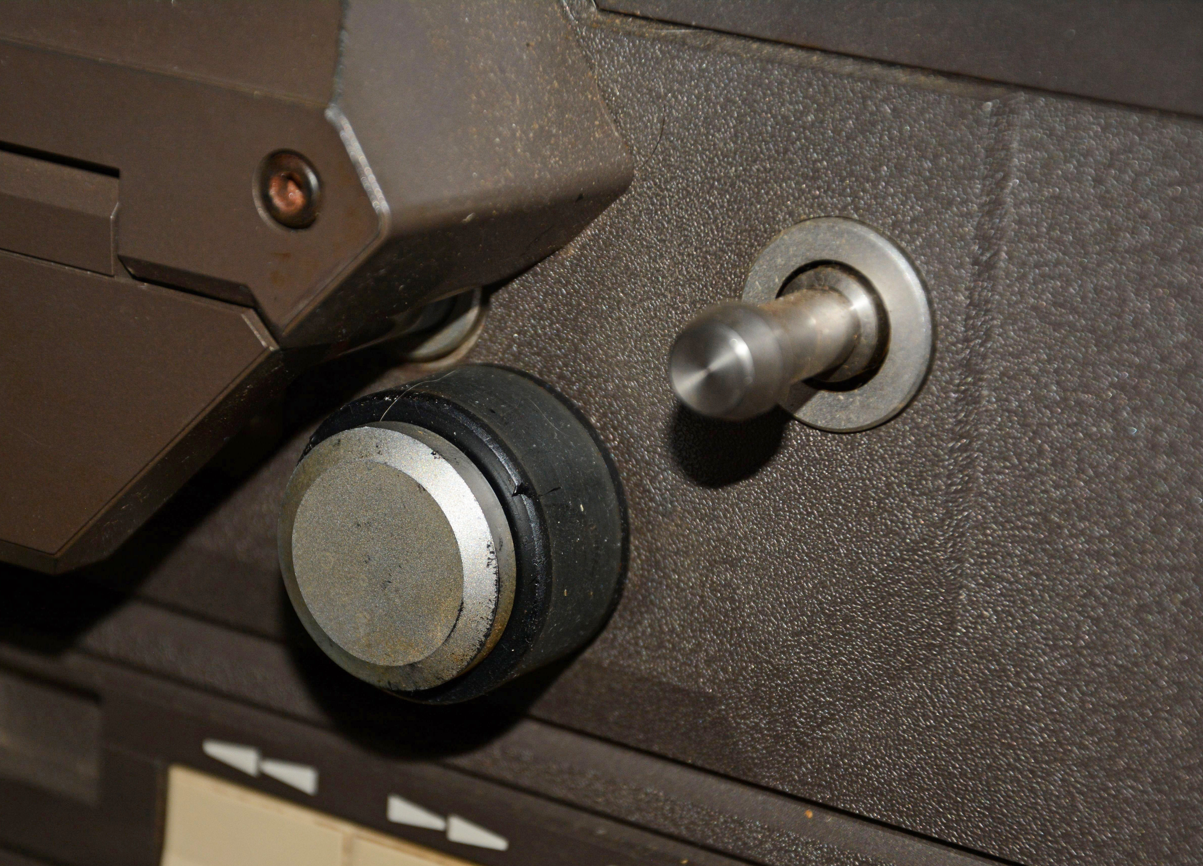
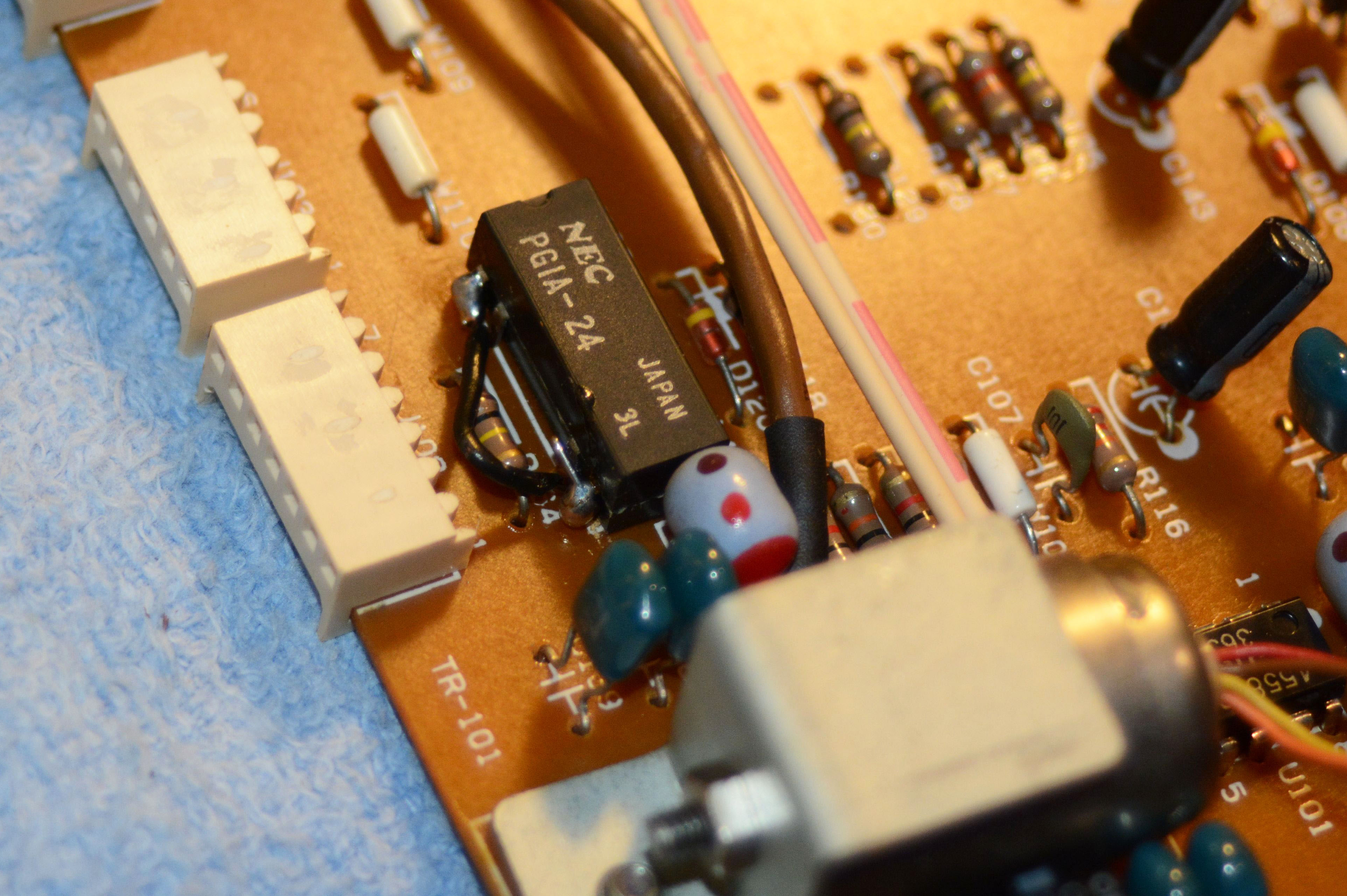
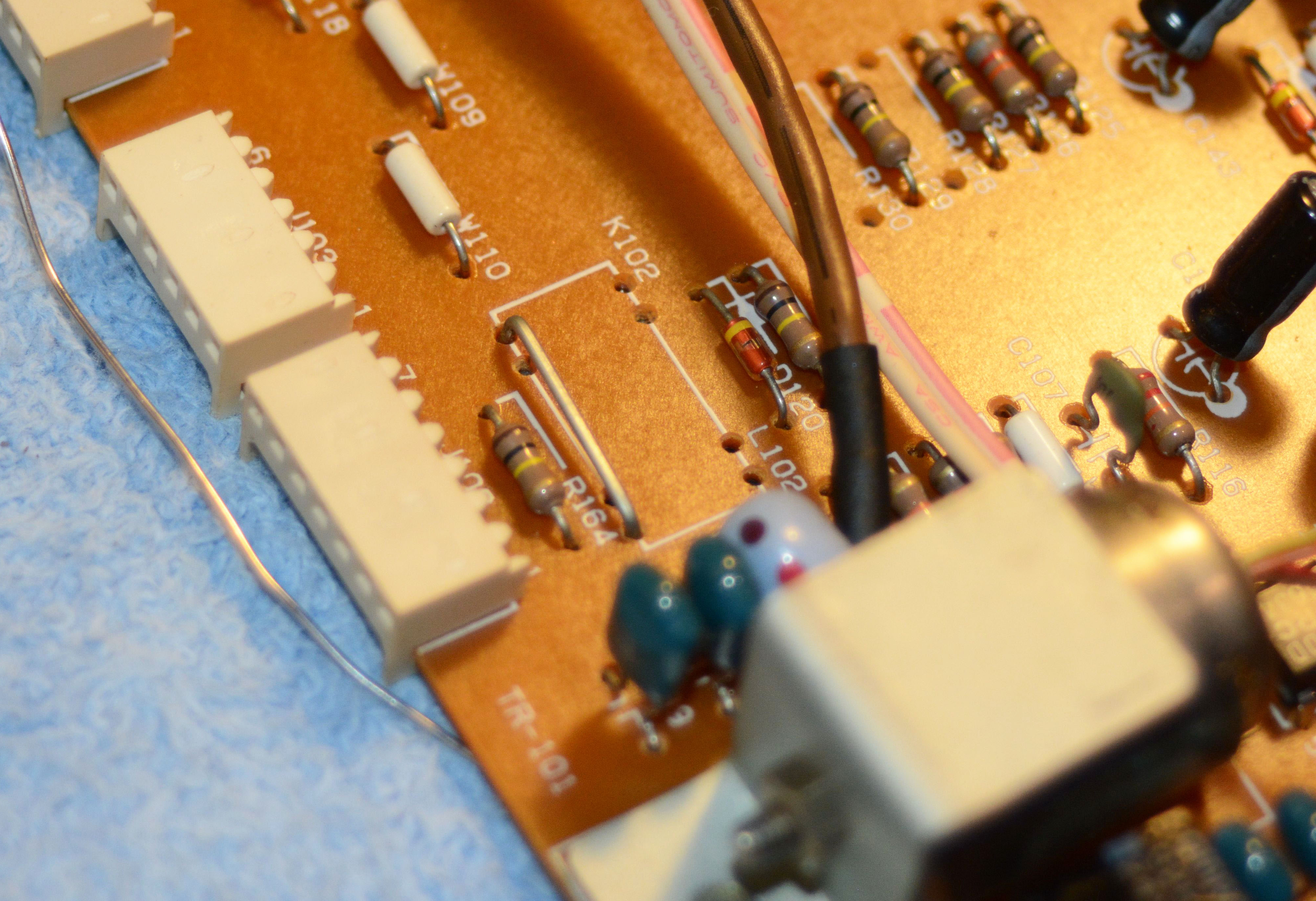
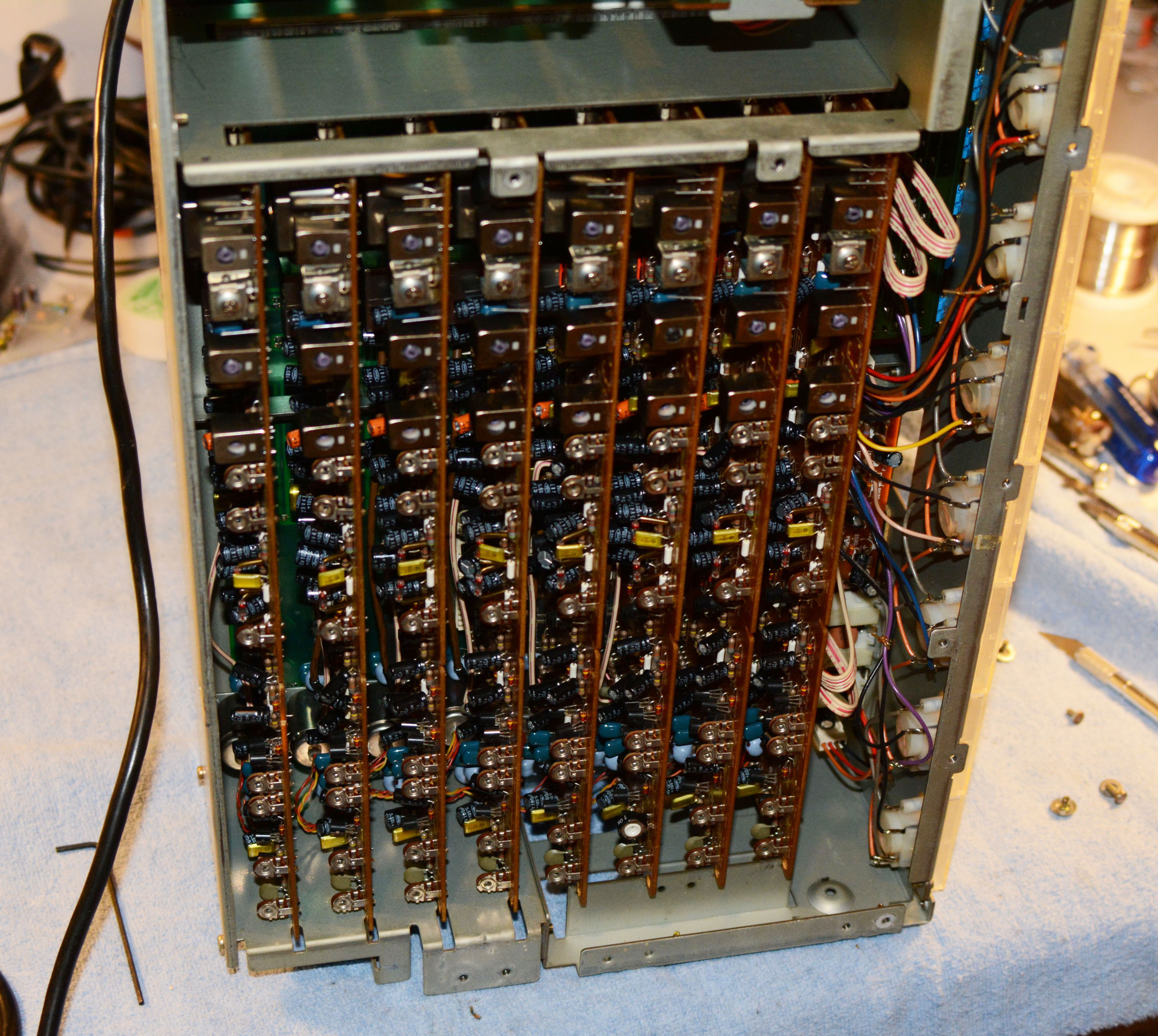
Also important is to refurbish the cylindrical dampers for the tension arms, if the old grease has become hard and sticky. I first tried NLGI #2 synthetic grease, but it was much too thin; in the end I settled on some "silicone differential fluid" from a hobby shop with viscosity 125,000 cSt. I didn't take pictures of this process, but there is a good forum thread with pictures in the Links section. The last thing to mention is bypassing the K102 relays on the channel boards. These relays mute the outputs until the power supply has stabilized, eliminating the transient signals that would otherwise pass when powering on and off. They are NEC PG1A-24 type, often have dirty contacts, and are sealed, so there are basically three options: "excercise" them to clean the contacts, replace them, or bypass them. On this machine, 7 of the 8 K102s already had the switch bypassed by a previous tech, either with a wire soldered across the pins, or with the relay completely removed and a jumper wire inserted. The only consequence of this is that the output is never muted, and there are transients when powering on and off, but it is not a big deal. Two of the relay bypass jobs are shown in the images below, along with a picture of all 8 channel cards, showing how they are mounted in the bottom:
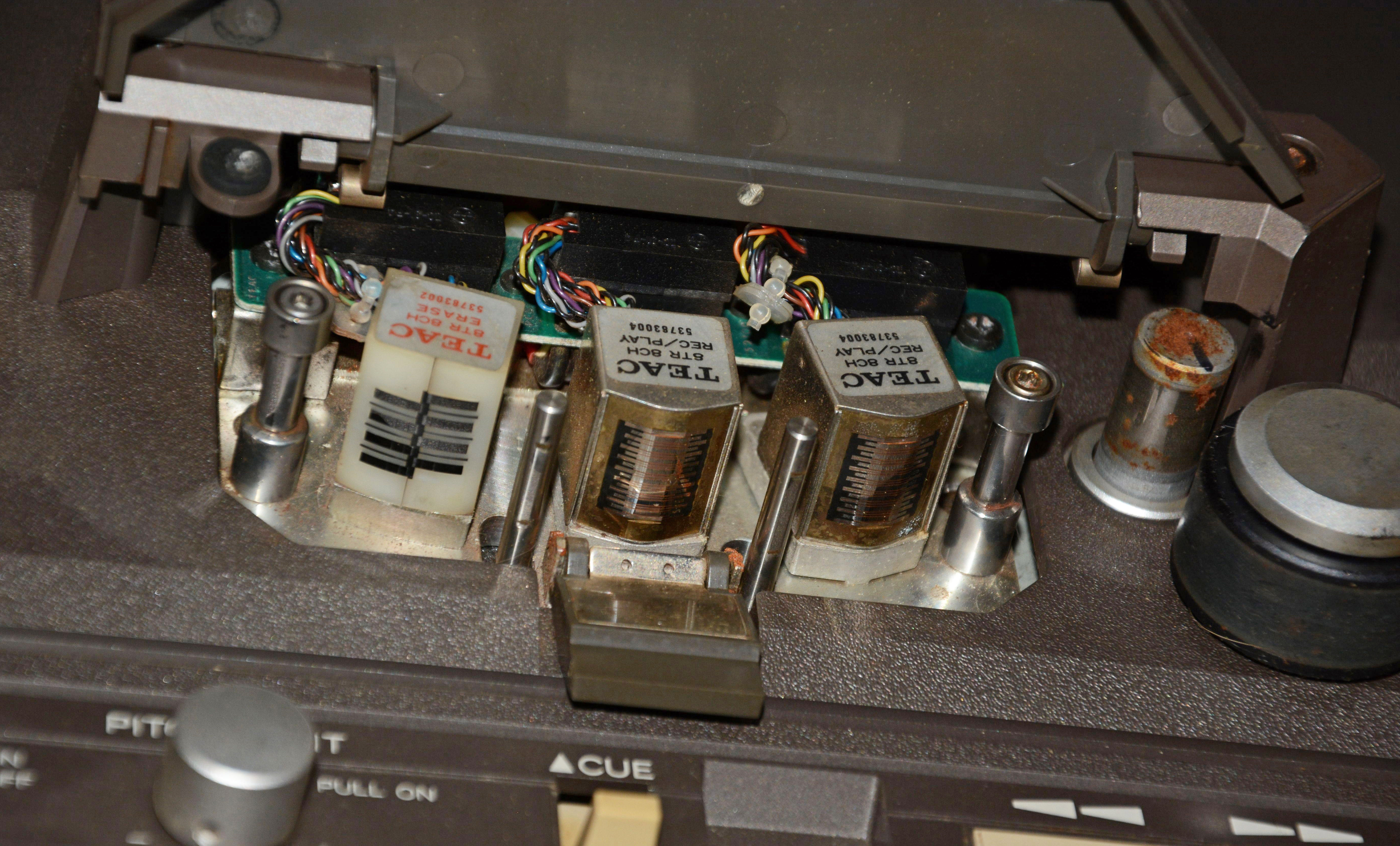
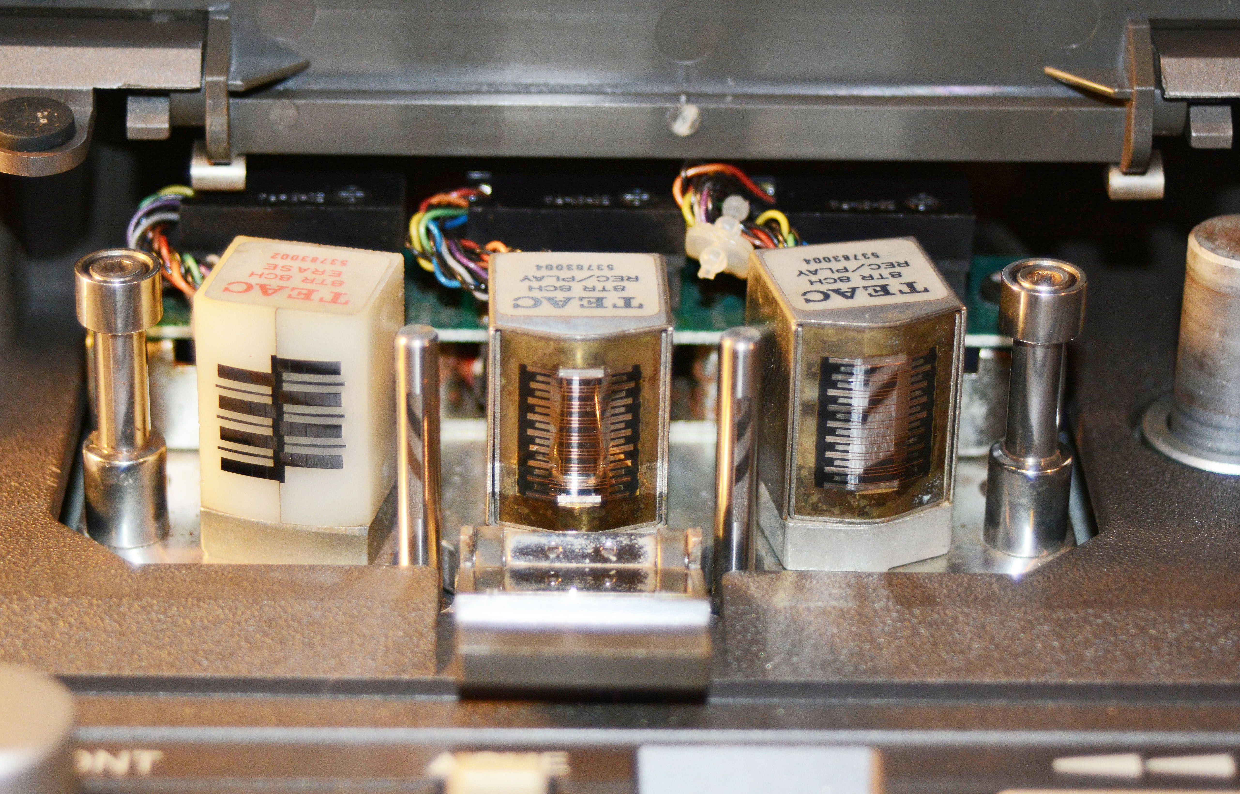
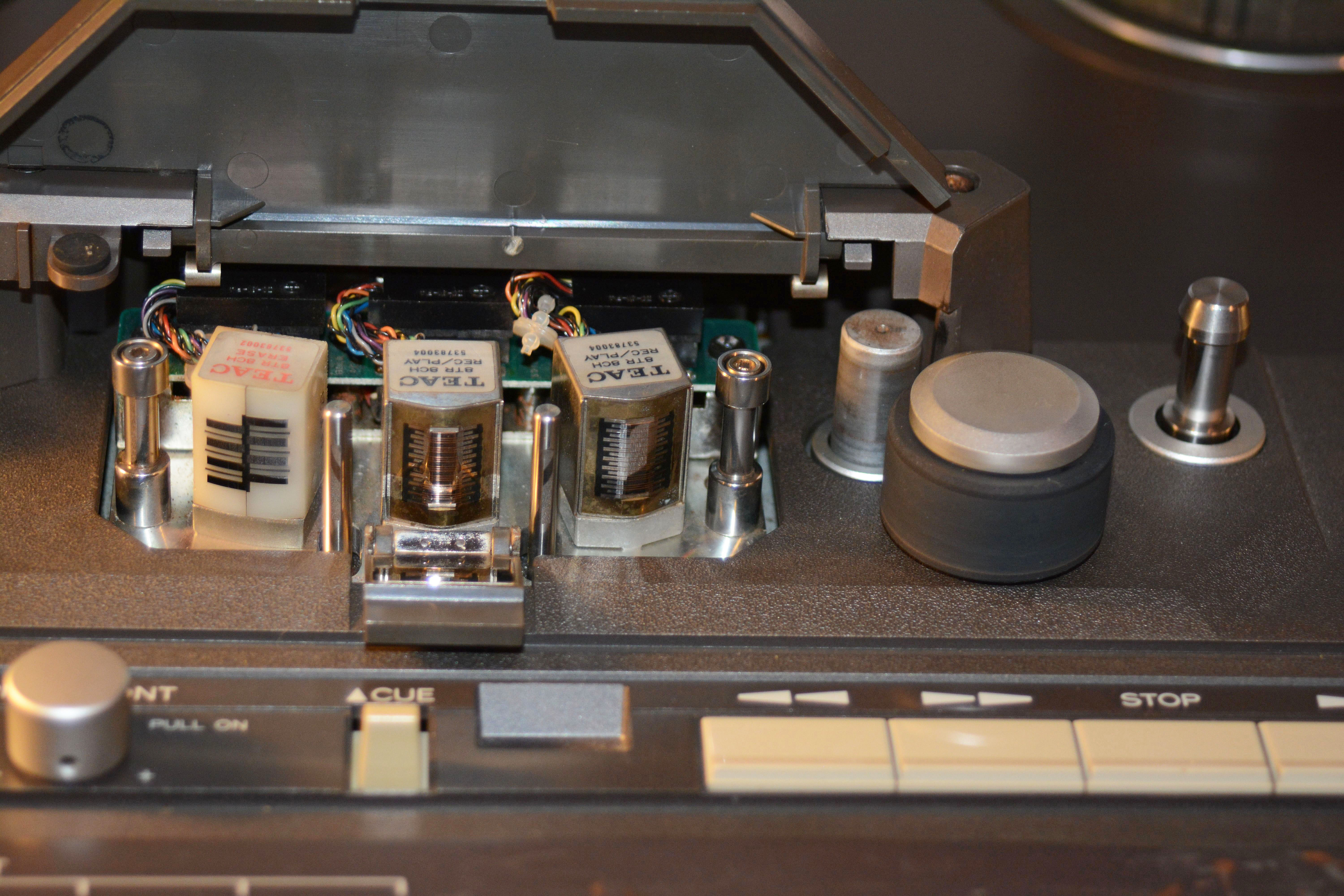
There are two more relays on each channel card: K101 which switches the preamp's input between the repro and sync heads, and K103 which switches on and off the bias signal to the erase head, and simultaneously switches the sync head between the bias+audio signal and the line going to K101. Simply put, K101 switches between repro and sync mode, and K103 turns on and off record mode. These relays cannot be bypassed, but can usually be cleaned up with exercise: repeatedly switching between play and sync modes, and going into and out of record mode. In the case of K101, which is an Omron G2E-184P, it has a tiny hole into which liquid cleaner can be applied, such as isopropyl alcohol or Electrosolve. I can't say for sure if this really does anything, but seems to have helped multiple times now, along with exercise. The Omron G2V-2 used for K103 is under a metal shield, but if you remove it, the relay's clear plastic top can be removed fairly easily, and the contacts cleaned. Finally, here are some shots of the head and capstan area after the repairs, showing clearly the cleaned tape path, new rubber on the pinch roller, and a resurfaced capstan:
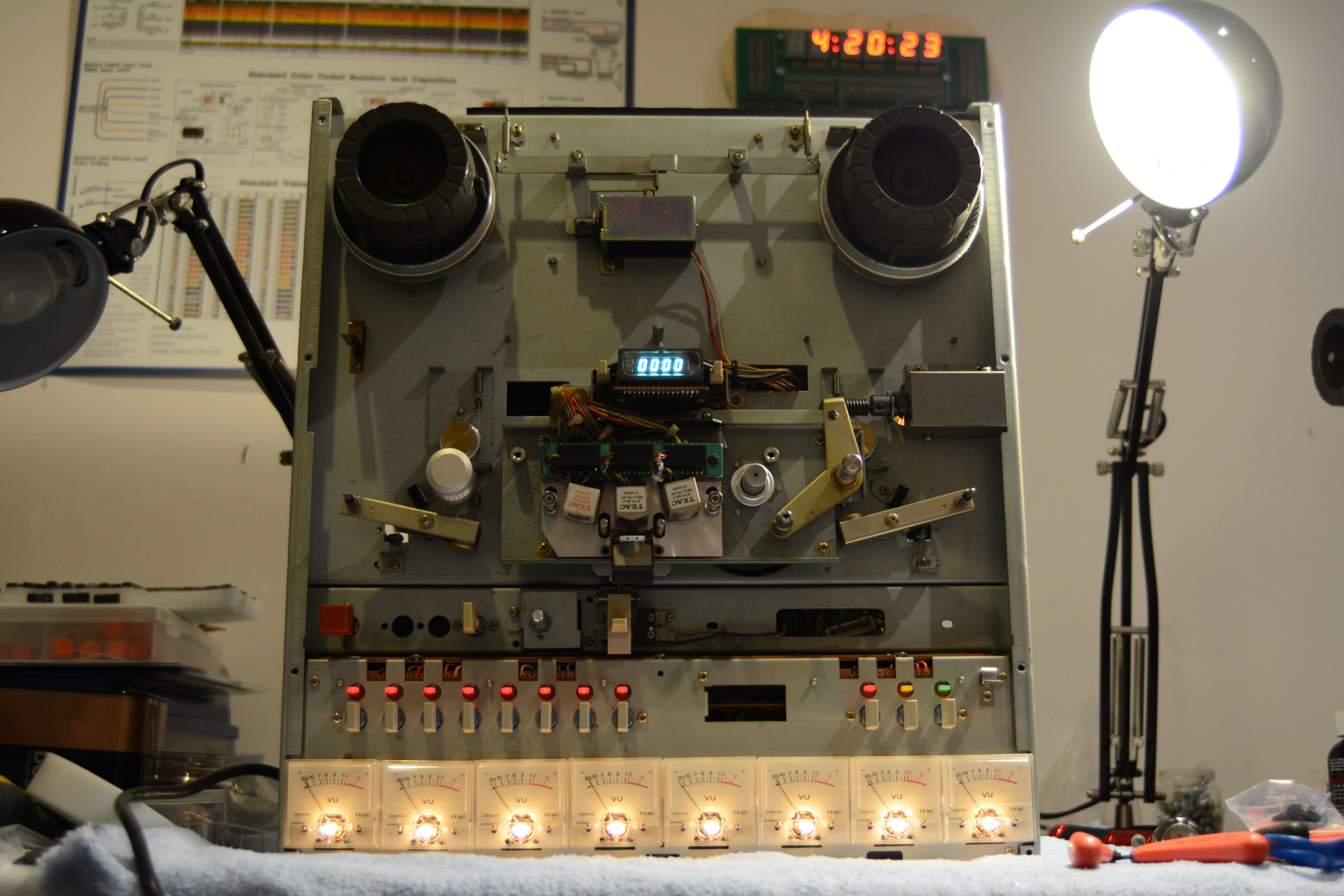
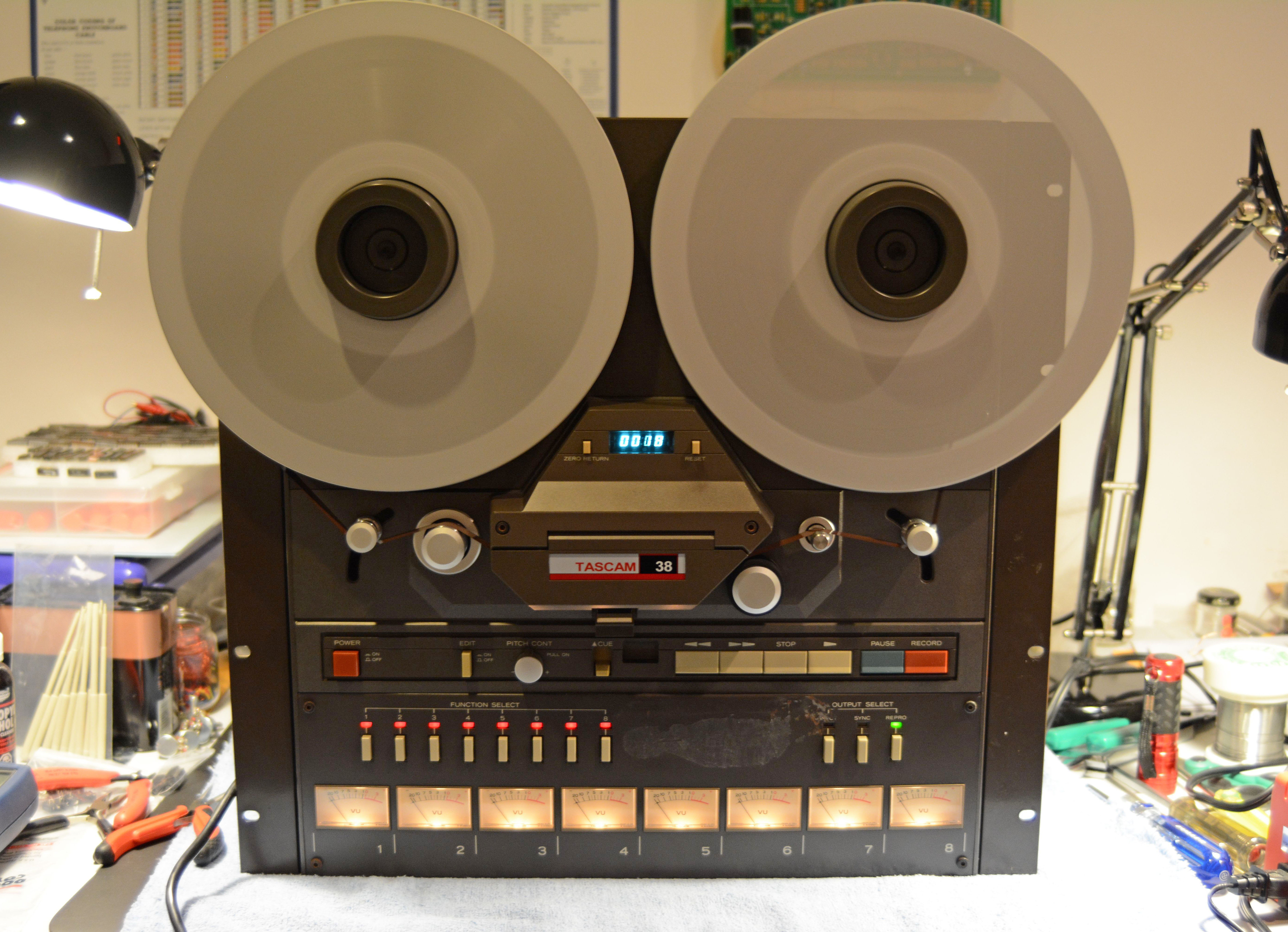
And the finished unit itself, aside from the addition of rubber feet:
Overall, this machine took a heck of a lot of work to bring up to spec, but certainly a fun sort of work. I'm quite happy and amazed with the result! In any case, if you have any questions about this machine and my repairs to it, feel free to ask. Links
|
| If you notice any errors or have additional information that you would like to add, please contact me! |