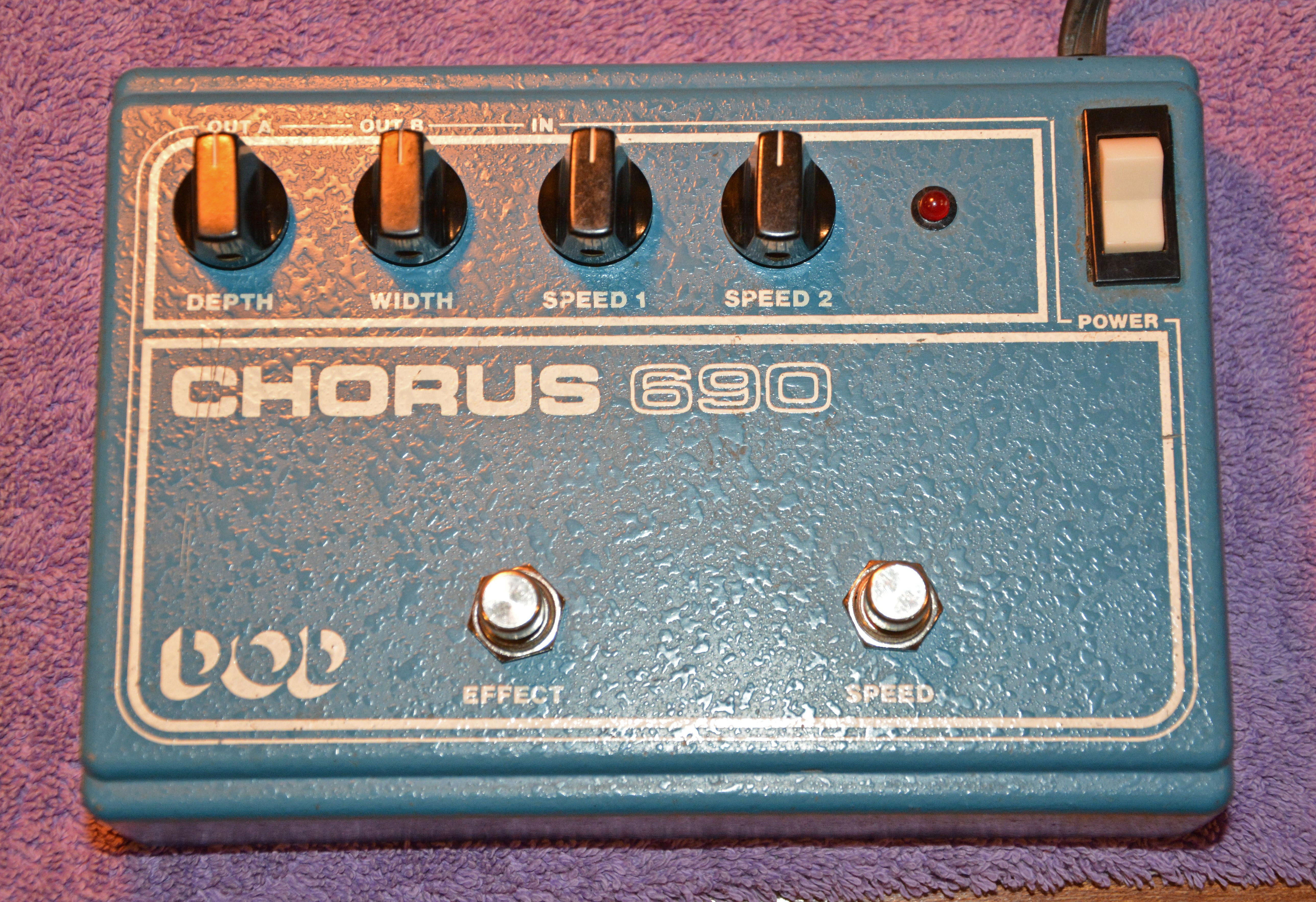
DOD Chorus 690Analog Chorus Pedal
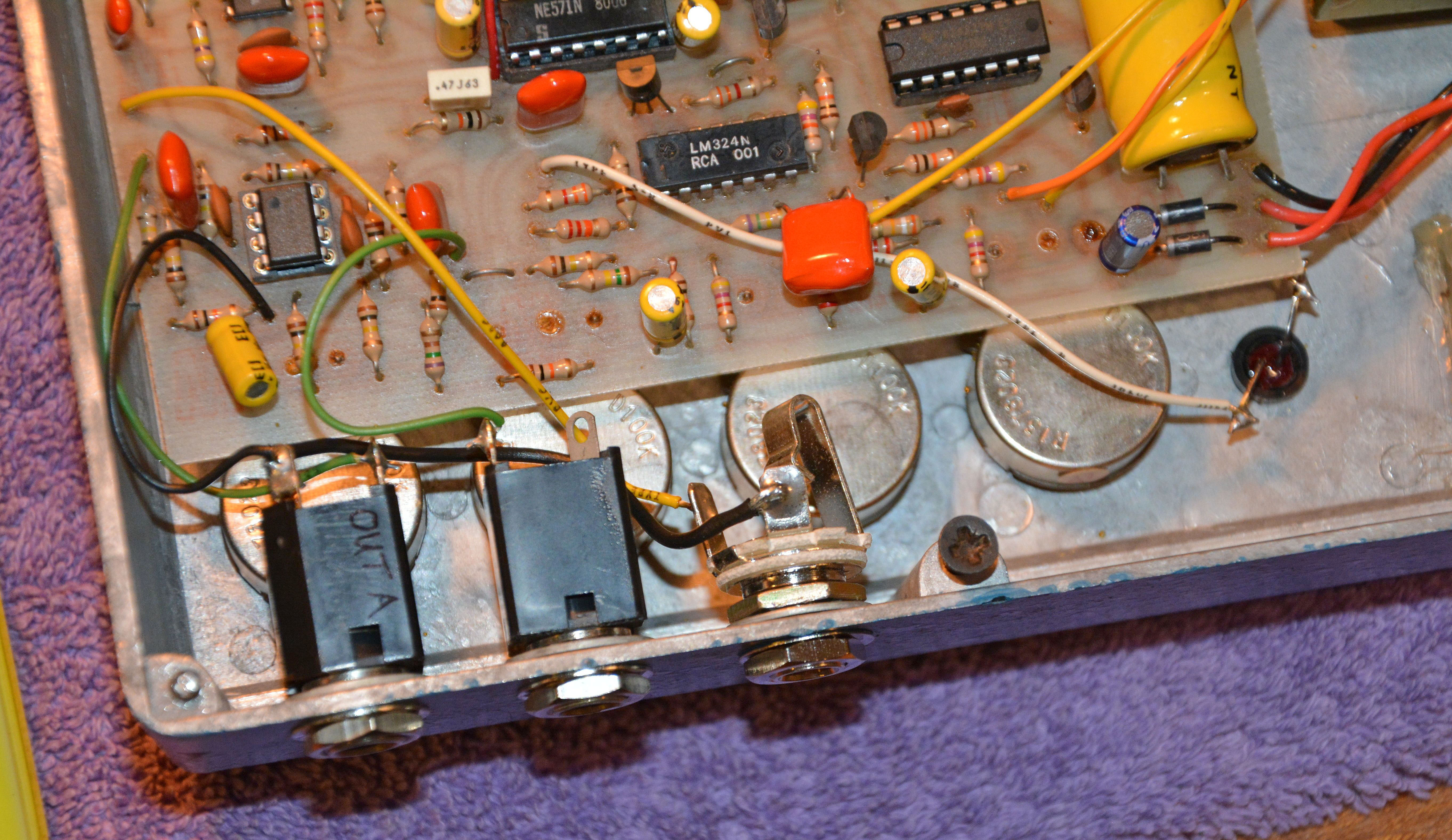
In mid-2017, I repaired this classic analog chorus pedal, made in 1980 by the original DOD Electronics company of Salt Lake City, Utah. As of this writing, this job remains my most extensive pedal repair, and I challenge you to find an even more laborious example! Despite its small size and relative simplicity, there were so many things wrong that by the end of the job, I nearly felt as though I'd built a new pedal. It must have experienced some catastrophic event, such as a severe electrostatic discharge, or a line voltage surge. What else could cause so many problems, yet cause no visible damage? To give a brief background, I bought this pedal for very little at a local music shop in mid-2016. It was missing the bottom cover (but not anymore; see addendum at bottom), which should've been an indication that all was not well, but I was told it worked. Of course, it was too good to be true—the pedal passed no distinguishable sound, giving only crackling noises. Alright, before we go on, have a look at the inside (after I finished repairs, since I forgot to take a shot before):
While not as simple as a fuzzbox, that's a pretty simple and serviceable pedal—it's a beautiful sight compared to the surface-mount abominations now dominating the market. I would not have attempted this repair if not for the spacious through-hole board and overall high quality, as well as the promise of a great sound. In any case, you may be able to spot some of the repairs done already, so I will simply list them all, followed by an account of how they came about. The repairs:
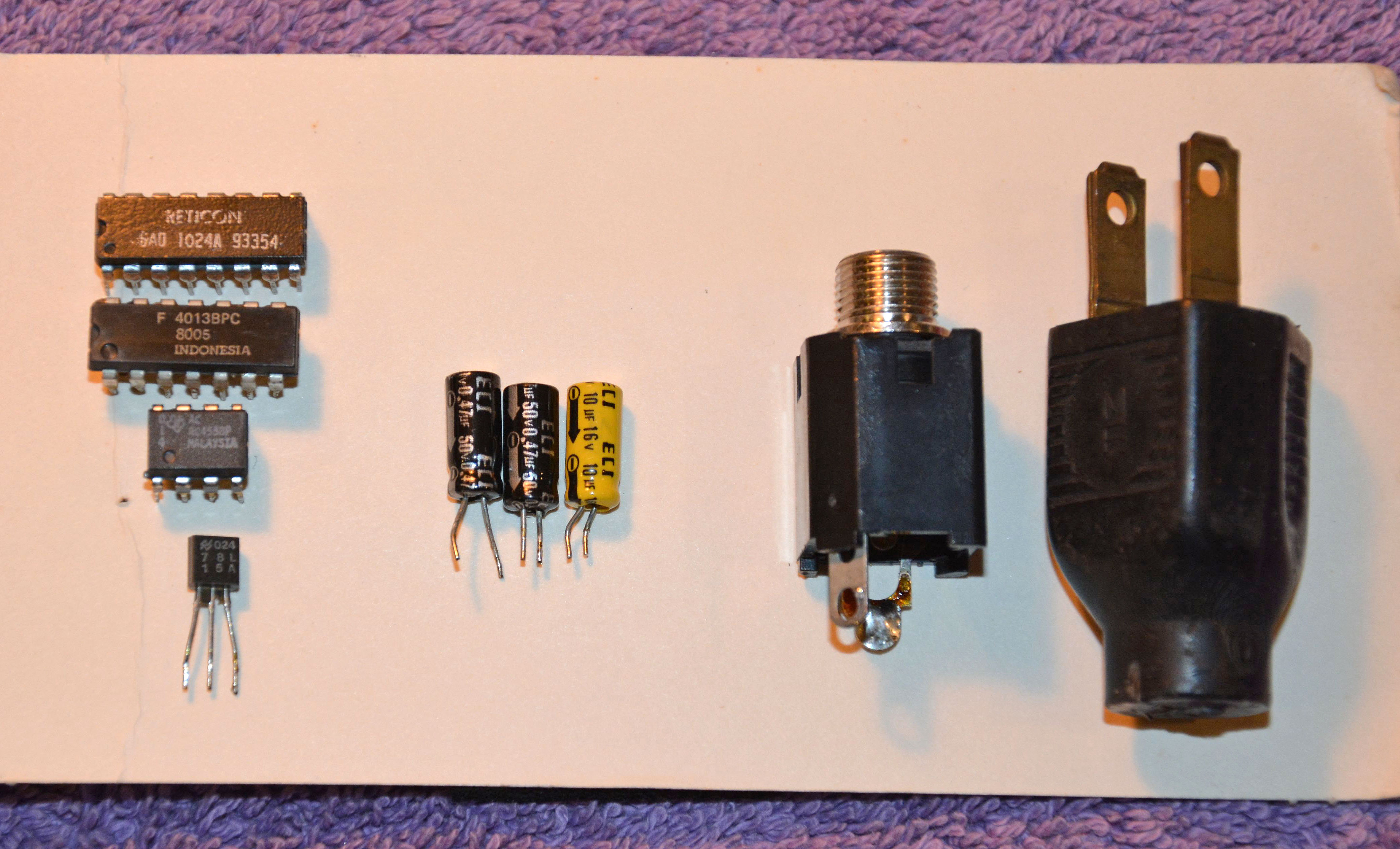
Also, for reference, you can find the schematic here. It is not an exact match, since it uses the SAD512D bucket-brigade chip instead of the SAD1024A, but it is close enough. Now, I'll explain the process behind these tasks. As always with things coming in so completely dysfunctional, the first thing to check was the power supply. It is an extremely simple circuit, giving only one DC voltage: +15V, regulated by a 78L15 chip. Viewing on an oscilloscope, this 15V rail looked terrible, switching frequently and sharply between around 6V and 15V. The 78L15 was getting very hot, indicating that it was being loaded down during the periods of low voltage. Nothing else was heating up much, so it was time to think. Since the correct voltage and decreased voltage were two distinct states and thus "digital" (with near-instantateous transitions between states), I suspected the only digital IC on the board: the 4013 dual flip-flop. Sure enough, removing it restored the 15V rail to a constant 14.7V. I then replaced it with a new TI part (CD4013BE), installing a socket for ease of future replacement. Since the 78L15 had been stressed, and was giving slightly low output, I replaced it as well as a precaution. Two parts replaced, and still, the pedal wasn't passing any signal. A feeling of dread began to manifest as it dawned on me that the SAD1024A bucket-bridgade chip may be at fault. This chip hasn't been produced for decades, and is now highly sought after, so the prices are ridiculous. My fears were given weight when I probed the first delay line of the chip, and although signal was reaching the line, no signal was passing through it... it was dead! This is the point at which many would've given up on this pedal, since they wouldn't want to bite the bullet of getting a new chip. After much deliberation, I went ahead and ordered the chip from an eBay seller, choosing a new-old-stock part in an Archer (Radio Shack) package that included the datasheet. A few weeks passed before the new chip arrived. When it did, I carefully installed it, and... barely any signal was coming through the first delay line, and its output was extremely distorted. I was momentarily paralyzed, but this was not the end of the world, since if you look at the board and schematic, you'll see something near the chip that's important:
That white 100kΩ trim resistor is used to adjust the DC bias of the signal fed into the first delay line. The datasheet gives the "Optimum Input Bias" as 6V, and sure enough, when I adjusted for about 6V at pin 2, the chip passed the signal much better. In the end, I adjusted the trimmer to allow the highest possible peak-to-peak input signal without distortion at the output. I also checked to make sure the original SAD1024A chip wasn't just biased incorrectly. Nope, it was definitely dead. If you guessed that signal still wasn't passing all the way through, you'd be right. The 4558 op-amp between the SAD1024A and the expander section of the NE571 compander was giving no output, and was getting warm—not normal. After replacing that with a socket and installing a NE5532 (another dual op-amp with the same pinout), finally, signal passed all the way through! And it sounded like utter garbage, with extreme amounts of distortion. Below shows the board with the new op-amp installed.
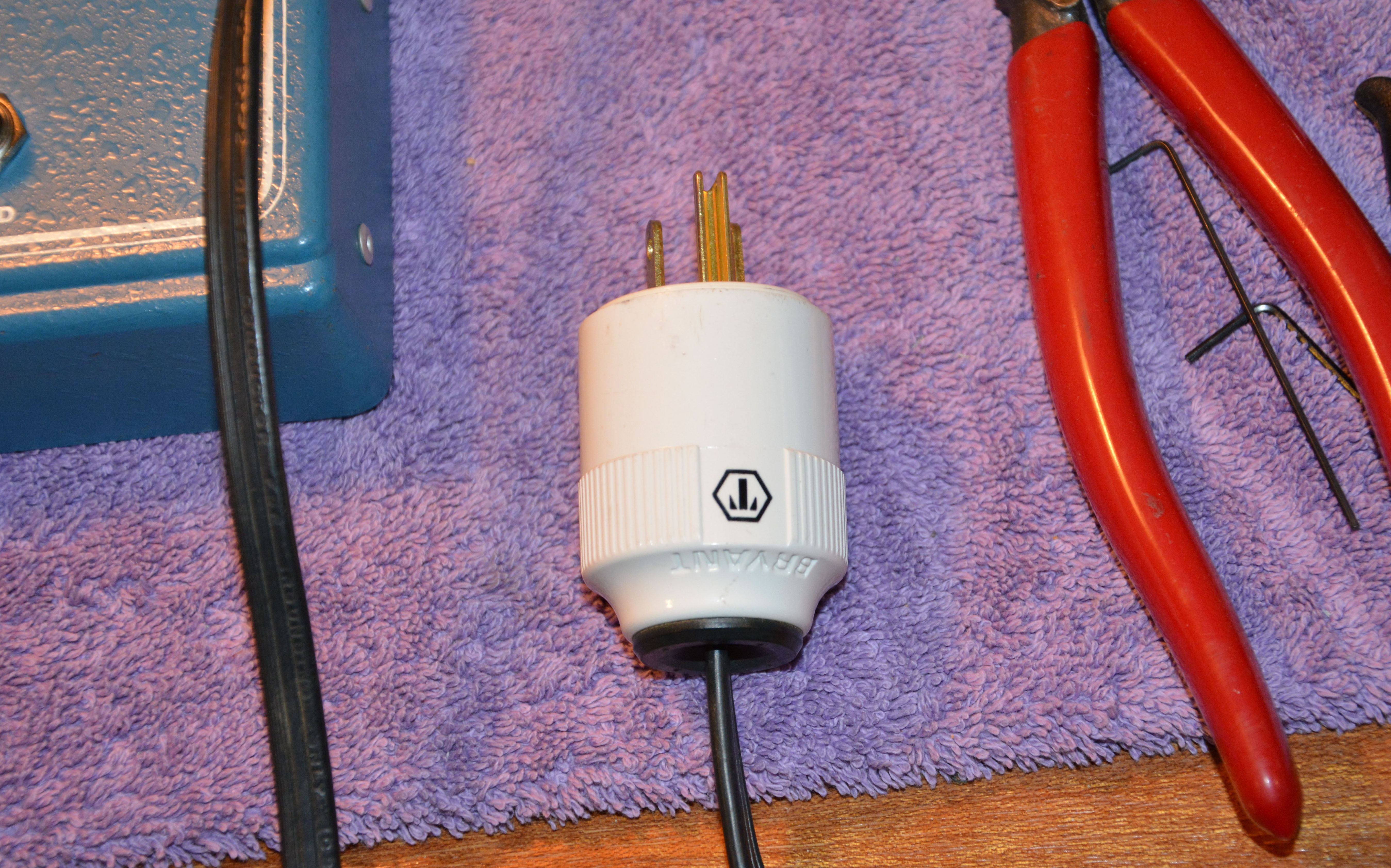
Good signal was going into the compander chip, and bad signal was coming out. Given that 3 of the 7 ICs were faulty so far (not even counting the 78L15), you'd expect the compander chip to be bad too, right? So, I ordered a new compander, swapped it (it was already socketed from the factory), and... the output was still distorted in the exact same way. Well, the compander chip has only a few supporting components, so it was easy to check them (which I should've done to start with). The resistors were good, as expected, but sure enough, one of the electrolytics was unmeasurable on my ESR meter, indicating it was open/dried-out/low-capacitance/etc. The bad cap was a 0.47µF 16V made by ECI, one of the few on the board with black wrapping instead of yellow. I replaced it, as well as another of the same type as a precaution (both of these with metalized film caps), and also one 10µF with excessively/unmeasurably high ESR. At last, the pedal passed signal, and was indeed sounding great! Lastly, I replaced the input jack since it was intermittent even after cleaning, and the power plug since it was missing the ground pin. I added a ground wire to the input jack sleeve.
And then it worked perfectly. Here's a picture of all the parts replaced in the end:
I should mention that there are two remaining issues (not related to functionality) that have not been addressed, which are the missing bottom panel and one broken-off screw. Unfortunately, a simple sheet metal panel would not work, since the transformer and jacks protrude further than the bottom edge. The original cast metal bottom would've cleared this. In any case, the owner of the music store continues to look for the panel, so one day it may be found. The screw can probably be drilled out. So, I hope this article has been interesting, and that it will help in the repair of more of these sorts of pedals as time goes on. If you have a broken Chorus 690 or similar that you don't want to repair yourself, I could repair it for you; see the Repairs page for more details. Addendum 12/31/2018: After more than two years of looking, the bottom panel was found by the shop owner! I should mention, for those in Edmonton: the shop in question is Lazaro's Music which remains the greatest place for vintage gear in town, by far. The proprietor, Errol Lazaro, is a kind and charasmatic guy. Note that the address on Google Maps is incorrect, since his current location doesn't seem to have a true address (otherwise I'd submit the change). His shop is in the same building as Revolution Cycle, in a spot easily visible from the inner parking lot.
Addendum 4/9/2020: How times have changed. Lazaro's Music sadly closed in June 2019, and we are now in the midst of a strange and highly propagandized pandemic. With my incoming repairs stopped for the moment due to the latter (and in order to finish various projects), I finally have time to work on some articles. Firstly, in late 2019, I assisted a fellow in repairing his Chorus 690 via email. The initial problem was that signal always passed through the pedal unaffected, no matter the settings. As inexperienced repairmen often do, he first attempted to fix it using a shotgun approach, replacing every socketed chip including the rare and expensive SAD512 bucket-brigade. When these replacements did not make any improvement, he contacted me, and I gave him some suggestions on how to diagnose the problem, mostly involving signal-tracing to isolate the faulty part. For some time and some reason, he still wished to avoid tracing the signals, so he purchased an ESR meter and checked the electrolytic capacitors. He found a few bad ones around the NE570 compander, and ended up shotgunning all of them. When this still made no improvement, he finally purchased an oscilloscope, and at last did some excellent troubleshooting, finding where the signal was really being lost. He first checked that clock signal was arriving at pin 1 of the SAD512D chip, and it was. Then, he found that no audio signal was coming into pin 6 of this chip, nor was there anything at the output pin 10 of the NE570 compander. Yet, signal was coming into the compander, and could be seen at pins 14 and 15! He then noticed that he had installed the replacement 4.7µF capacitor between pins 10 and 14/15 backwards, and upon reversing it, audio then passed to the SAD512D's input. Still, nothing was passing through the SAD512D. It had input, clock, and power, so what else could be wrong? Well, he found that his replacement SAD512 did not pass signal, while the original did just fine! (Whether this was due to the new chip being improperly biased or truly defective is unknown.) At last, after reinstalling the original SAD512 and adjusting bias slightly, the pedal worked. So, what was the problem to begin with? Probably just the bad electrolytics around the NE570 compander, with a parts cost of less than $1.00, and replacement time less than 30 minutes. Though he eventually solved this, he inflicted two new problems in the mean time: a backwards electrolytic, and a bad SAD512. If he had started with real diagnosis in the first place, he could have saved a great deal of time and expense. Of course, I don't write any of this to insult the guy, since after all, he learned his lesson and did good work in the end. Rather, I hope this serves as a lesson to others: don't just shotgun or try to replace the same things that other people have replaced. Keep in mind our reports, sure, but first and foremost use your intellect and some basic tools to find where things are really going wrong. Do not focus only on the parts that are easiest to replace (such as socketed ICs), or that have a reputation for unreliability (such as electrolytic capacitors). Faults are often very simple and easy to fix, but only if you know how to find them. All of the necessary equipment for real troubleshooting can be had for lower cost today than ever before, and once you develop the skills, you will find they are applicable to a wider variety of situations than first expected.In March of 2020, I received another Chorus 690 for repair, shipped to me by a fellow in Toronto. He had purchased it on Reverb as working, yet when received, he found the speed indicator LED had sunken into the chassis and shined with constant rather than oscillating brightness, and the effect had no modulation no matter the settings. So, he sent it to me. Once received, I started by checking the low-frequency oscillator circuit. This is built upon two sections of the LM324N quad op-amp, connected in a positive-feedback arrangement with a 2N4124 transistor also as part of the loop. As suggested by the constant LED brightness, no oscillation was present, despite a good SPEED switch, good transistor (using a quick diode test), and a good 10µF electrolytic (in terms of ESR). So, I removed the LM324 and installed a socket. Then, I tried a standard TL074 quad op-amp, which has the same pinout and supposed functionality. While this revived the LFO, the op-amp section driving the BBD clock oscillator did not behave as desired — its output was always pegged close to the positive rail, turning on the 2N4124 transistor fully, thus making the clock oscillator stop running. Two new TL074s did this, so it was not a bad chip. I ordered and installed a proper LM324N, and then the LFO modulated the BBD clock properly. This goes to show that in certain circumstances, the specific type of op-amp can make a difference. Also, I noticed that the WIDTH could be made considerably "wider" than on my pedal, and in fact much wider than one would use under normal circumstances. I suspected a bad electrolytic, and the customer wanted a "recap" anyway, so I did the recap and tried it again. Sure enough, the width control had a normal adjustment range after the recap. One of the 10µF caps tested very badly, and some of the others were slighly off. Stupidly, I didn't pay attention to where the bad 10µF came from, but I bet it was the one that filters and attenuates the LFO signal after the width control (in parallel with a 10kΩ resistor). I also bolted in the transformer, since its rivets were loose. During this process, I found that one wire was too short to allow the transformer to be mounted flush with the chassis. This implies that the loose rivets may have been that way from the factory, in order to compensate for the too-short wire! I lengthened the wire and installed bolts with thread-locking compound and lock-washers.As a last mention, I should point out something about all Chorus 690 pedals: they do not have sufficient input gain to be used with a raw electric guitar signal — the output from typical pickups will not come anywhere near the pedal's maximum input level, and thus the pedal's output will have to be amplified to compensate for this, causing the clock noise of the bucket-brigade chip to become very obvious and irritating. The best thing to do is to place a preamp pedal (or some effect with a reasonable amount of gain) before it. If you use a long chain of pedals to begin with, it should be placed near the end of the chain. Downloads & Links
|
| If you notice any errors or have additional information that you would like to add, please contact me! |


First Published: 09/15/2018