Hammond S-6Electronic Chord Organ
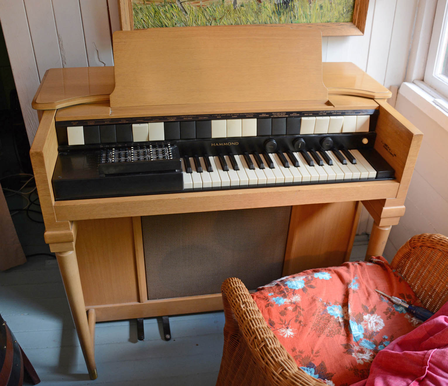
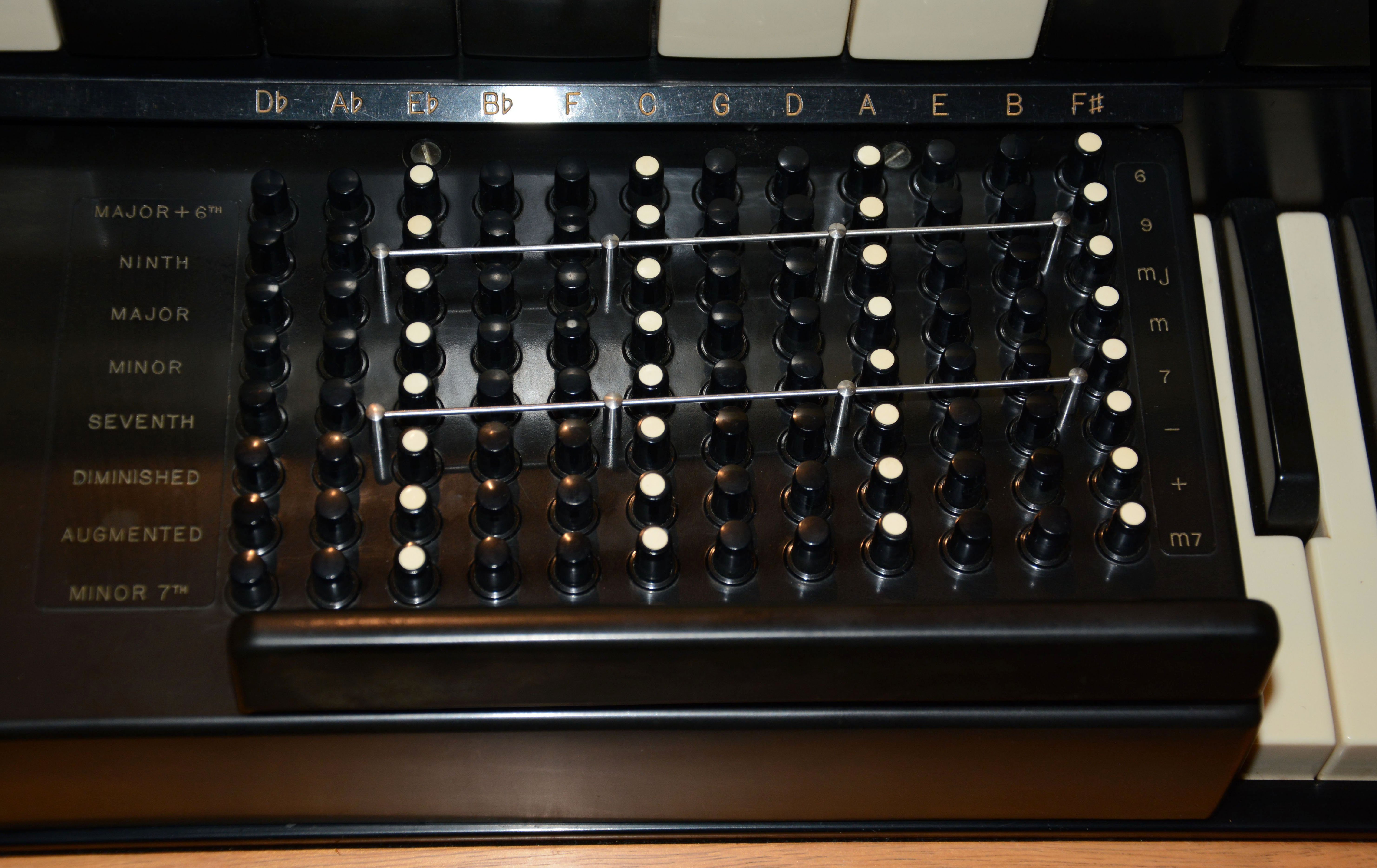
In this article, I will discuss the Hammond Chord Organ, and especially the model S-6, which is certainly among the most well-known and enduring vacuum-tube instruments of all time. Unlike Hammond's tonewheel organs, which are electromechanical, the Chord Organ is completely electronic, using vacuum-tube circuitry to both generate and amplify its sounds. It has three divisions (or "voices", if you prefer): a "chord" division controlled by 96 buttons and two pedals, a timbrally versatile but monophonic "solo" division, and a semi-polyphonic but less timbrally variable "organ" division. Besides that the "solo" and "organ" divisions share the same 37-key manual, the divisions are basically independent, each having a separate set of tone generators. Thus, slight tuning differences result in a rich true-chorus sound when the divisions are played together. Despite the lack of shared components between divisions, Hammond's ingenious and elegant designs result in a very economical and compact instrument, as far as vacuum-tube organs go. Models prior to the S-6 use only 29 tubes, while the S-6 uses 30 due to the addition of "percussion" (replacing "accent") in the solo division. It should be noted that the chord organ was a Hammond invention, introducing many playing features never before seen. For example, in front of the chord buttons, there is a "chord bar", played by the left wrist, which sounds the chords fully when pressed, and either completely or partially dampens them when unpressed. While chord buttons themselves are not new (being a feature of accordions for over a century prior), the arrangement is different from any accordions that I know of, and the variety of chords is greater. The two bass pedals are a remarkable feature; the left bass pedal plays the root of the selected chord, and the right plays the fifth, making for extremely easy bass accompaniment. Rather than use an expression pedal to control its volume, the S-6 instead uses an expression lever moved by the right knee, which also serves as the power switch. At this point, there are two S-6s in the Crasno collection: a form "B3" from 1956, and a form "B" from 1958, shown in the left and right images below the title respectively. The difference in form is almost completely a matter of styling. Of all the keyboards in my collection, the S-6s rank highly. They not only have a rich and distinctive sound, but are especially fun to improvise on, since it is so easy to play a chord and bass progression while soloing with the right hand—that was basically the point, after all. There are no modern equivalents of Hammond's chord organs in sounds nor capabilities (and especially not in build quality), and so I hope this article assists in repairing, preserving, and otherwise increasing knowledge of these fine instruments. If you have a Hammond chord organ in need of repair, and could bring it to my shop in Edmonton, Alberta, Canada (since I do not perform house calls), I would be happy to repair it. Please seem my Repairs page for details on rates and policies. I can also provide some guidance by email. Features
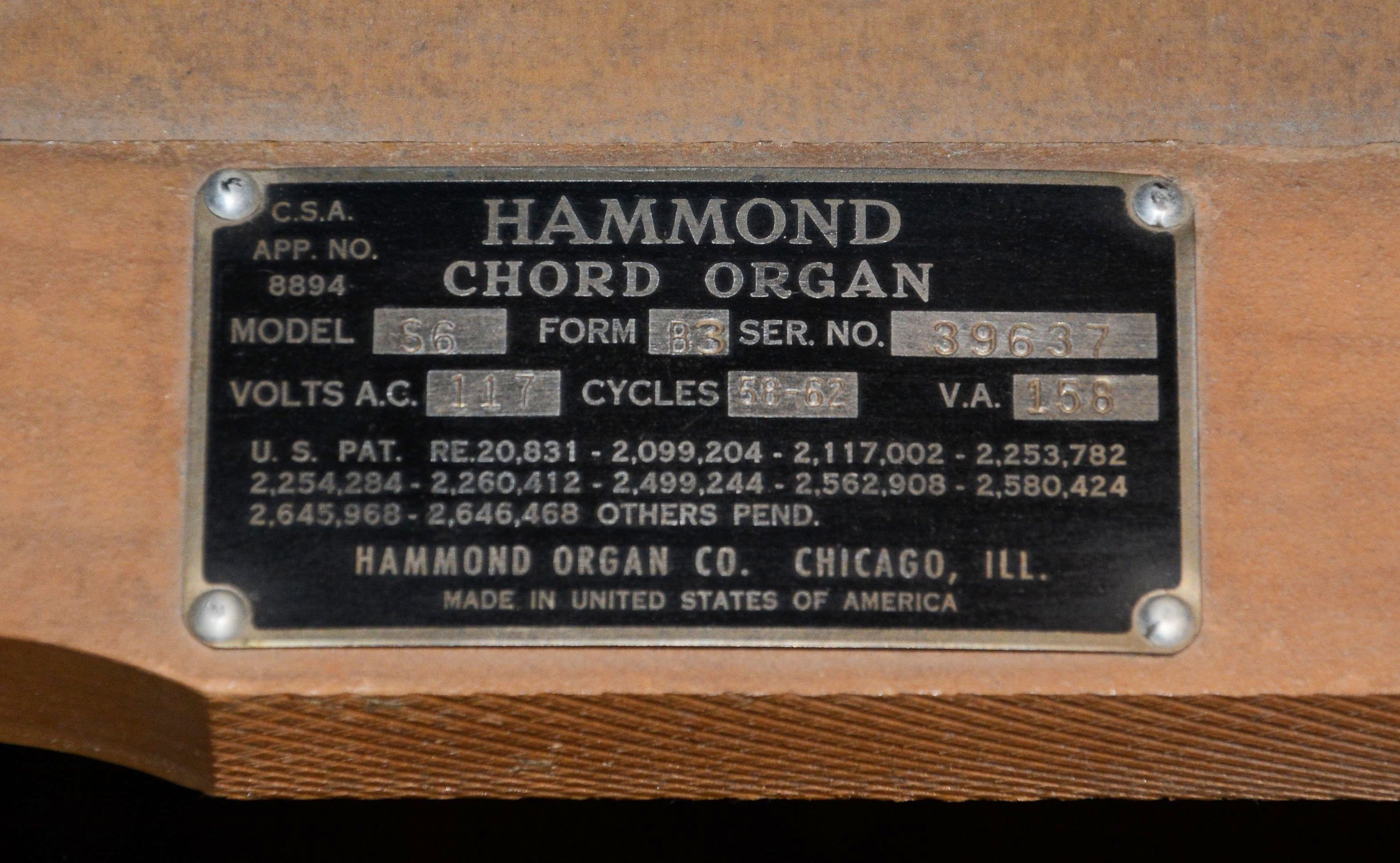
HistoryFor this section, I will largely direct you to other sources, while compiling the most important info from them. Wikipedia's Chord Organ article provides some interesting facts, one being that the Hammond company (of Chicago, Illinois) invented the first chord organ: the model S, introduced in 1950. The main inventor was John M. Hanert, Hammond's lead designer at the time. He previously worked on the Novachord, Solovox, and even the original tonewheel-based Model A. The Novachord is sometimes considered the first polyphonic synthesizer, making use of ADSR-like volume envelopes and versatile filtering based on "formant" principles. The Solovox is a monophonic instrument whose technology was adapted into the "solo" voice of the chord organs. Of course, I hardly have to explain the significance of Hammond's tonewheel organs. In fact, Hanert was perhaps the most prolific and innovative electronic musical instrument designer of his era, having filed roughly 90 patents between 1939 and his death in 1962, mostly relating to electronic musical instruments and effects. A short biography of Mr. Hanert can be found here. Hammond made at least ten chord organ models, which are the S, S-1, S-4, S-6, S-100, S-101, S-112, S-133, 2022, and 2044. The first three are practically identical functionally and tonally, but the model S uses all octal tubes and a 12" field-coil speaker, the S-1 uses mostly miniature tubes and a 12" field-coil speaker, and the S-4 uses mostly miniature tubes and two 10" alnico speakers. Model S-6 is like S-4 except instead of having a "solo accent" tab that merely adds a percussive volume accent to the start of the note, the S-6 has a "solo percussion" tab that makes the overall volume envelope percussive, meaning that it decays to silence, similar to a plucked or hammered string. My impression is that the S-6 was the most popular model of all, since it remains the most commonly found by far, and was produced longest. Note that the model name is often condensed to "S6", and in fact Hammond used both forms; e.g. in the manual, it is called "S-6", while on the builder's plate, it is "S6". The S-100 series instruments are very similar to the S-6, except that they use an expression pedal instead of a lever, and have built-in spring reverb. The circuitry is still entirely vacuum-tube. As with other Hammonds with three numerals at the end of the model designation, the last two digits indicate variations in cabinet style and finish (replacing the "form" designation of the older units), while the electronics are basically identical. Starting in 1967, the 2000 series chord organs were produced, which are the models 2022 and 2044. It appears they were usually branded "Hammond Everett Series", considering the instruments may have been based on Everett designs, and that Hammond acquired Everett Piano Company in 1962. As compared to the S series, they are very different functionally and tonally. Instead of independent sets of oscillators for the organ and chord sections, both sections share signals from a common set of 12 master oscillators with 3 frequency dividers each. Hence, these organs do not exhibit the richness of the S-series' slightly-detuned independent oscillators. The organ section is more versatile, having two registers (8' and 16') instead of one, and eight timbre tablets instead of two. However, there is no solo division whatsoever, and instead of eight chord types, there are only four: major, minor, seventh, and diminished. Tone generation is transistor-based, while the vibrato oscillator and amplifier circuits use tubes. Many parts previously made of wood or metal were changed to plastic, or otherwise cheapened. The expression pedal uses a potentiometer, which is a cheap and unreliable choice as compared to the variable capacitor previously used. You can smell the cheapness looking at pictures, which are easy to find. Overall, while still worthy of some praise, the 2000 series are inferior instruments as compared to their predecessors. (And let's not even mention the unbelievably cheesy plastic Hammond "Sounder" chord organ made from 1973 onwards...) Much of the info above was from Hammond Organ Club Holland. From their info, I have also prepared a timeline of chord organ models:
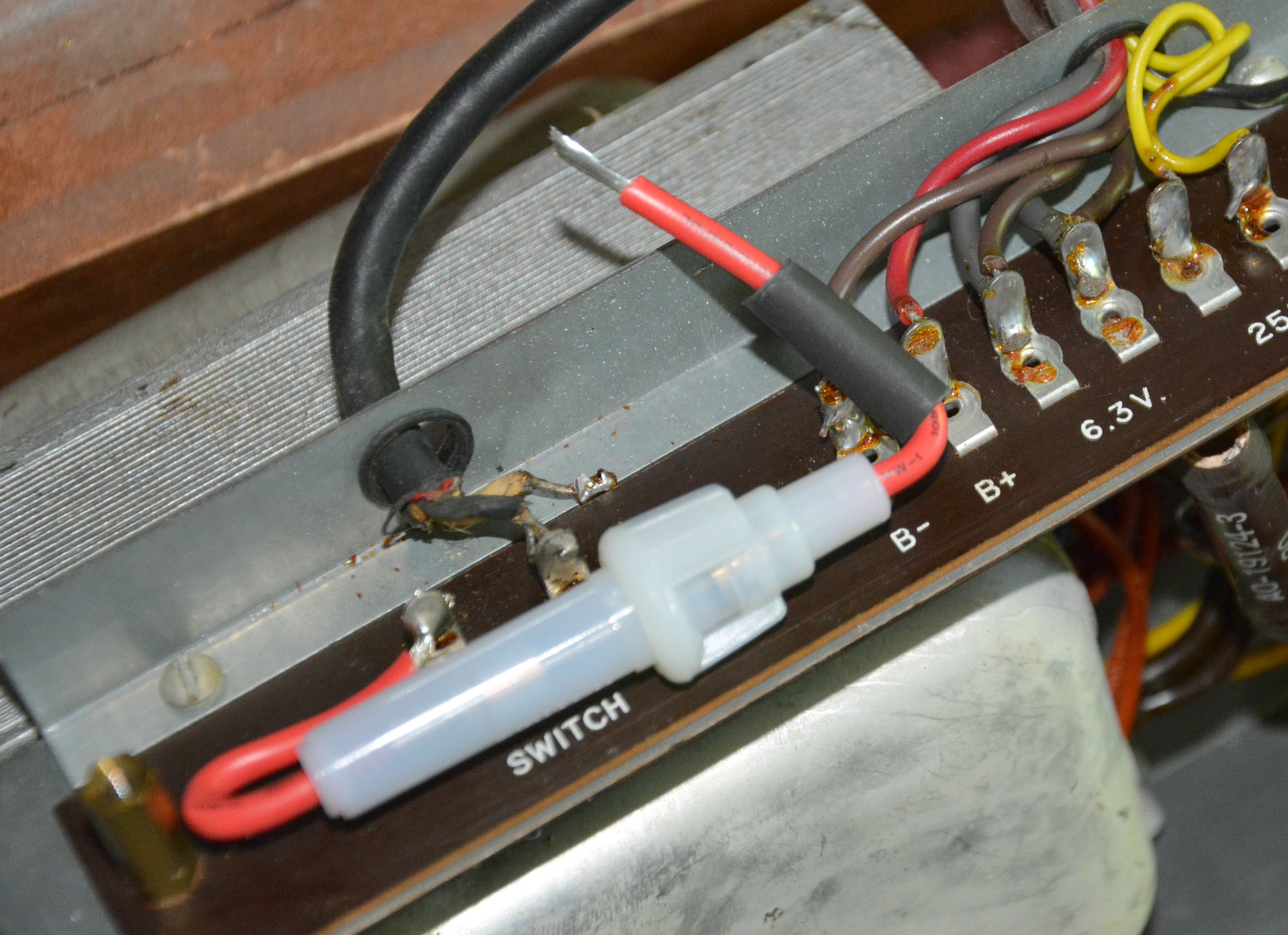
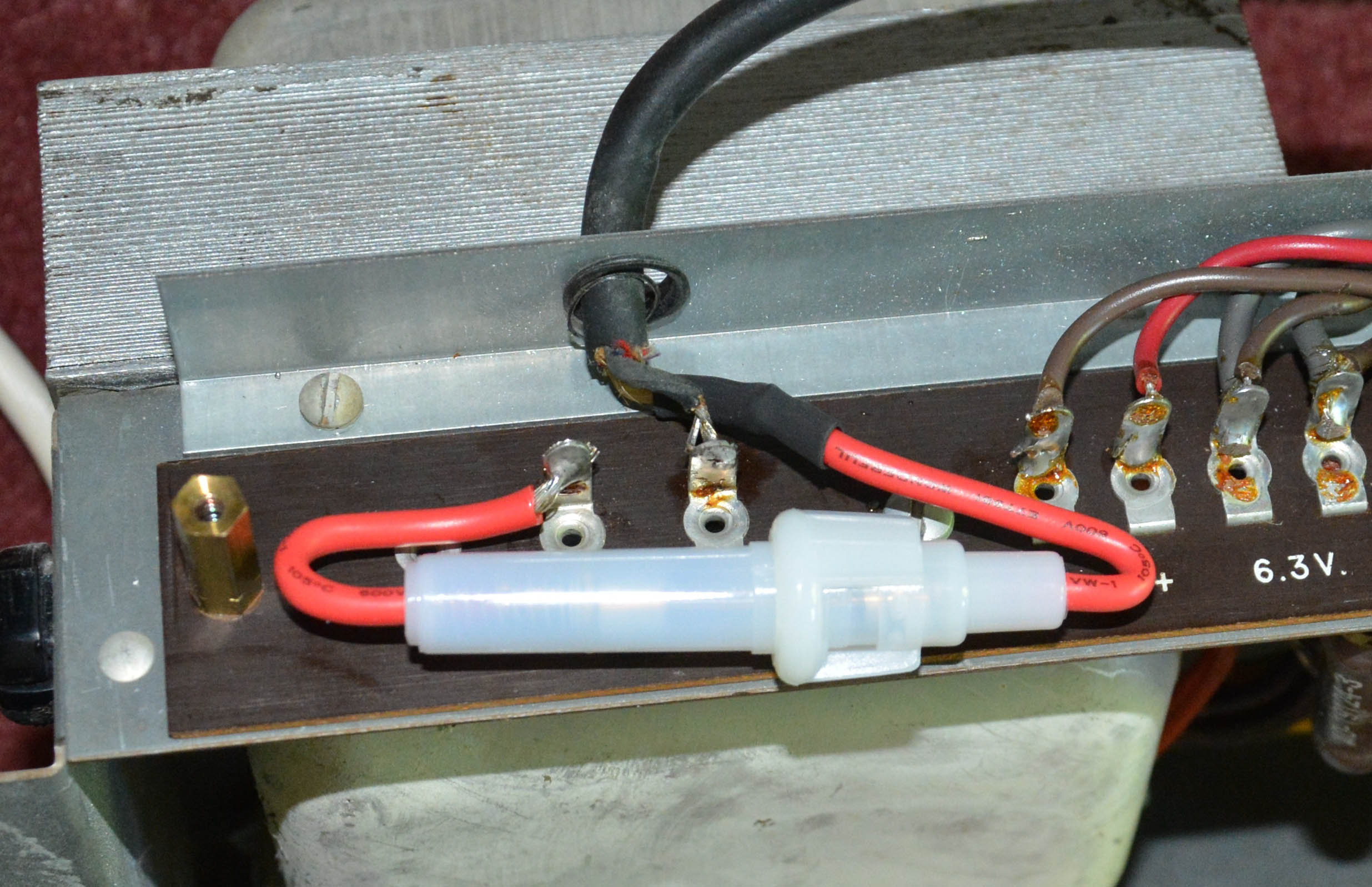
For a decent "historical perspective" article, see this one on WorthPoint. To conclude this section, I will mention some developments that arose from Hammond's chord organs. Firstly, John Hanert's last commercial design for Hammond was the F-100 "Extravoice", produced from 1961 to 1964. It can be thought of as a more serious and versatile form of the chord organ, though it isn't one; the circuits, and hence the sounds, are much the same, but it has no chord buttons. Instead, it has a 52-note manual and 13-note pedalboard. The manual controls the semi-polyphonic "treble" and "accompaniment" sections (much like the "organ" circuits of the chord organs), as well as the monophonic "Extravoice" section, which is nearly the same as the S-6's solo voice, but with another frequency divider (providing the "Contra-Bass" register) and some control differences. The pedalboard uses a completely independent oscillator similar to that of the "Extravoice" section, but capacitance-controlled. Prior to 1958 or thereabouts, the Minshall Organ company of Vermont made an unusual type of electronic chord organ, which is referred to briefly in Electronic Musical Instruments, 2nd Edition by Richard H. Dorf. It had a 48-key manual and 10 chord-selector buttons, the latter being the unique feature; rather than the chord buttons sounding chords on their own, the lowest 12 keys were played along with these chord buttons to give 120 possible chords: more than any other chord organ that I know of. From the image in the book, the arrangement looks somewhat awkward to play, though the instrument seems well-built and attractive in design. Note that I am using the past-tense here because it appears that virtually none of these instruments still exist; besides a story about someone's mother selling them in the '50s, and a copy of Dorf's text, I could find no other references online whatsoever to Minshall's chord organs. If you own one, or have additional info, I would be interested in knowing. Hammond's electronic chord organs also gave rise to millions of much cheesier reed-based chord organs blown by electric motors, starting with Magnus in 1958, and expanding to include such brands as Antonelli, Bontempi, Briscoe, Farfisa, Orcana, and Orla, some of whom also produced decent electronic instruments. These are typically quite inferior, usually having a comparatively limited chord selection, only a single rank of reeds, no bass section, poor cabinet acoustics, and a loud blower motor. For awhile, they tainted my perception of reed organs, but it was much improved after playing an old-fashioned harmonium... what a difference a bass end, multiple ranks of reeds, and a big resonant wooden cabinet makes! Also, in 1971, the Optigan was introduced: a unique chord organ that obtains its sounds from concentric optical tracks on interchangeable plastic discs. On most discs, the 21 chord buttons (three chord types of seven roots) key looped recordings of real bands playing the particular chords. Tempo is adjusted by increasing or decreasing the speed of rotation, which consequently shifts the pitch. There are separate tracks for each key of the 37-note keyboard, and because they are looped, there is no limitation on note duration, unlike the Mellotron and Chamberlin. However, the recorded track therefore cannot have attack nor decay. It would've been possible to implement such characteristics electronically, but it was surely deemed unnecessary given the Optigan's market: inexperienced players of modest means. In fact, its toylike design and build is a result of coming from the toy manufacturer Mattel. Yet, the Optigan appears to have more of a cult following than any other type of chord organ! Of course, the idea of a keyboard with easy-to-play bass and chord accompaniment has been developed into the only form still manufactured today: digital keyboards that will give you the approximate sound of a whole band with the press of a single key. Such instruments I consider highly inauthentic and un-musical—I consider them only suitable for parodical "nusic". Power Supply Fuse InstallationBefore explaining the repairs, there is an important modification to mention. Despite that it was common practice by the 1950s, Hammond did not fit their chord organs with a line fuse in the power supply, so I recommend installing one. Such a fuse will blow and thereby protect the organ if it draws excessive current because of a component failure. For example, if one of the filter capacitors shorts, or the rectifier tube shorts, then it is quite possible for large amounts of current to be drawn, potentially causing the power transformer to overheat and burn out, or for certain resistors to go up in smoke, or for the capacitors to vent their electrolyte. Any of these could happen without the house breaker tripping. So, if you own a Hammond chord organ, I recommend performing the modification I am about to describe, or have a competent technician do so. It is relatively easy, and I've even prepared a set of instructions at the request of a reader:
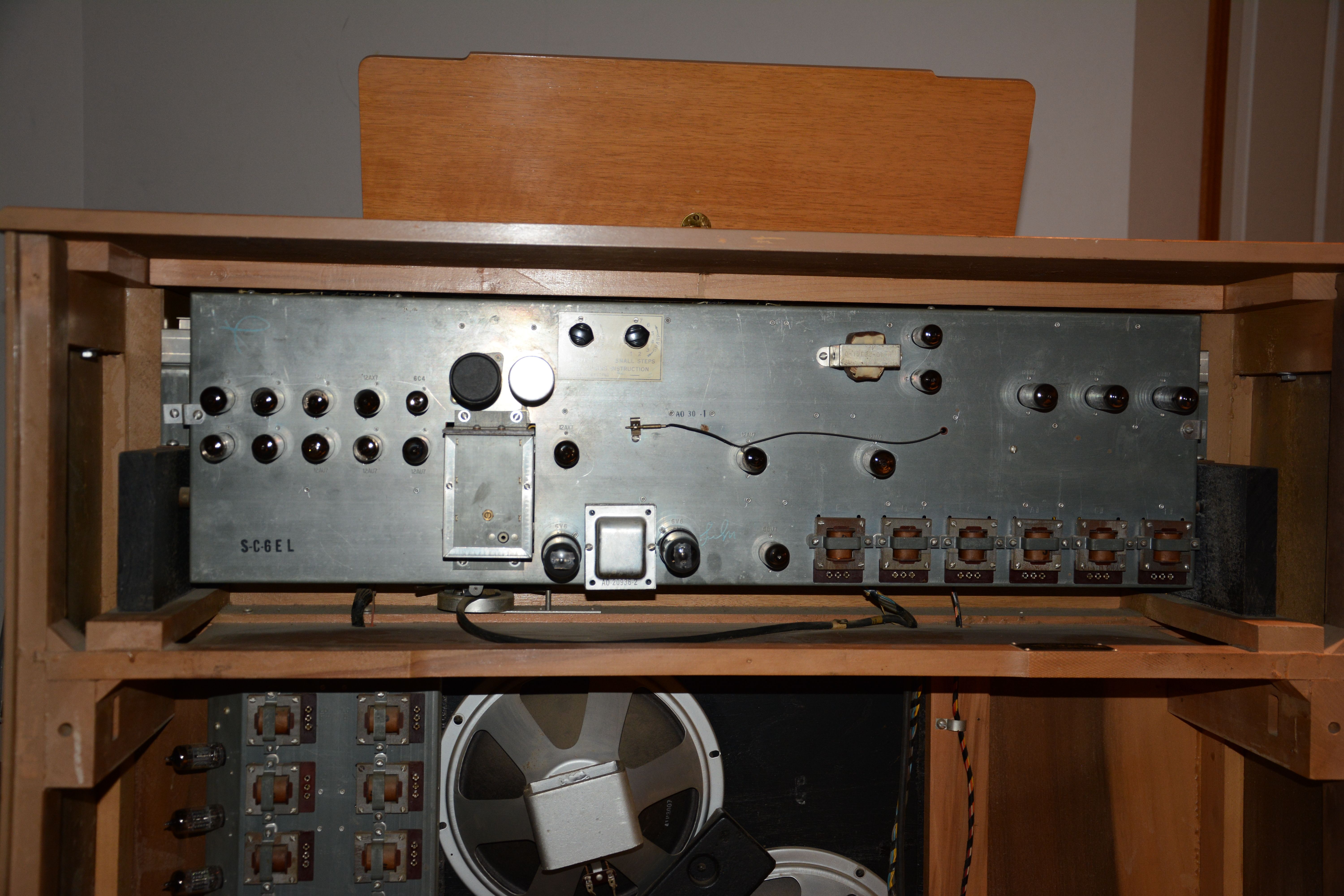
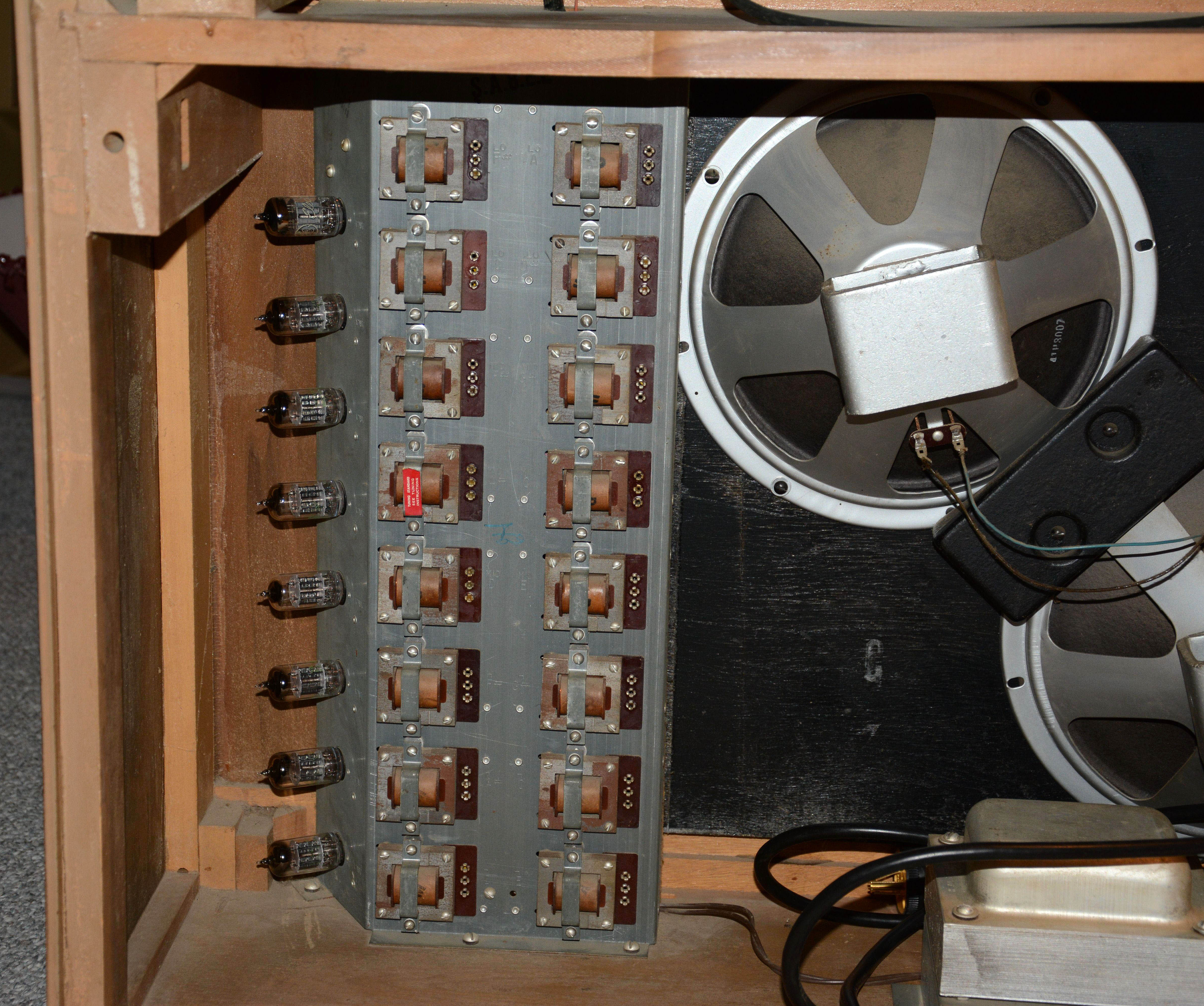
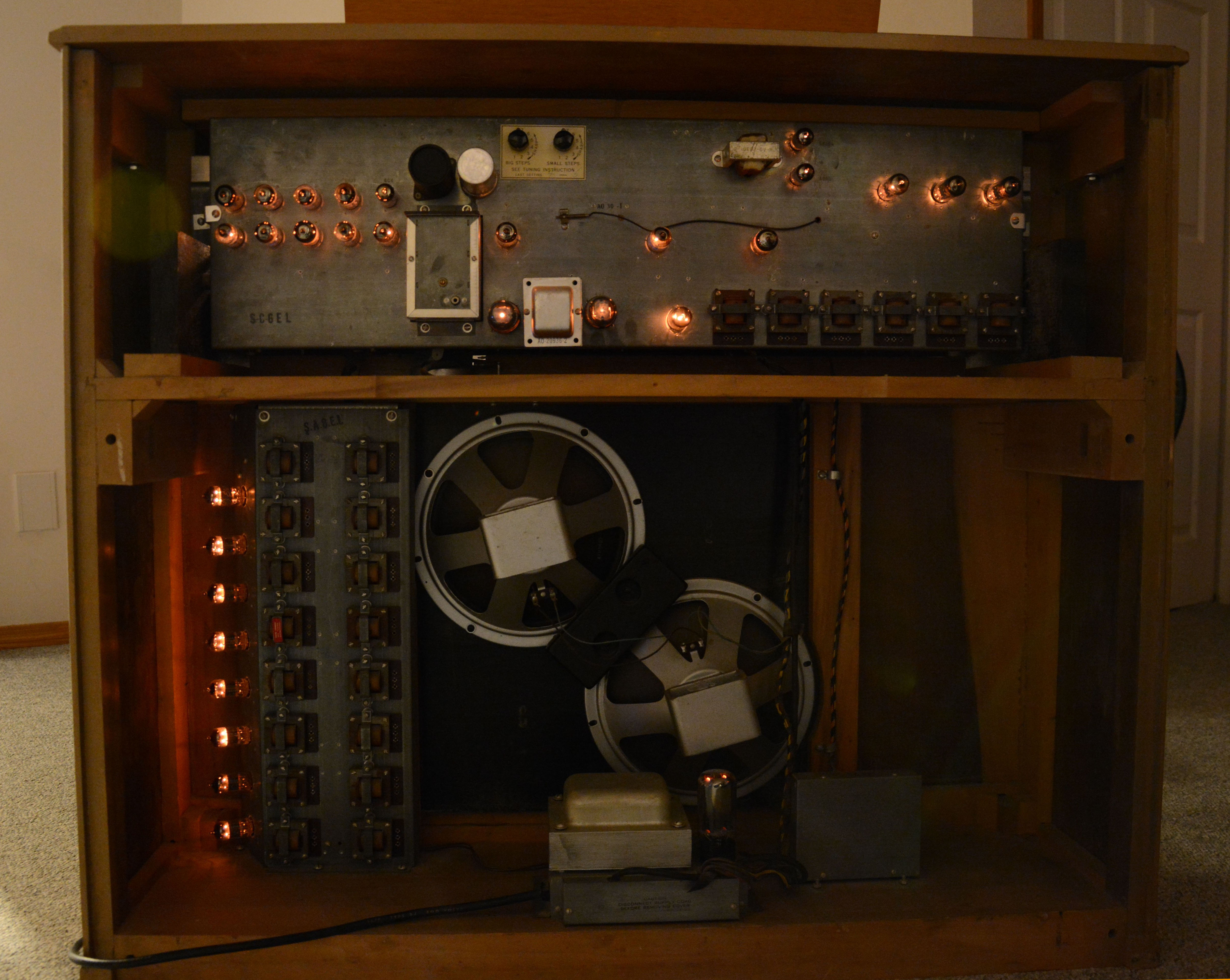
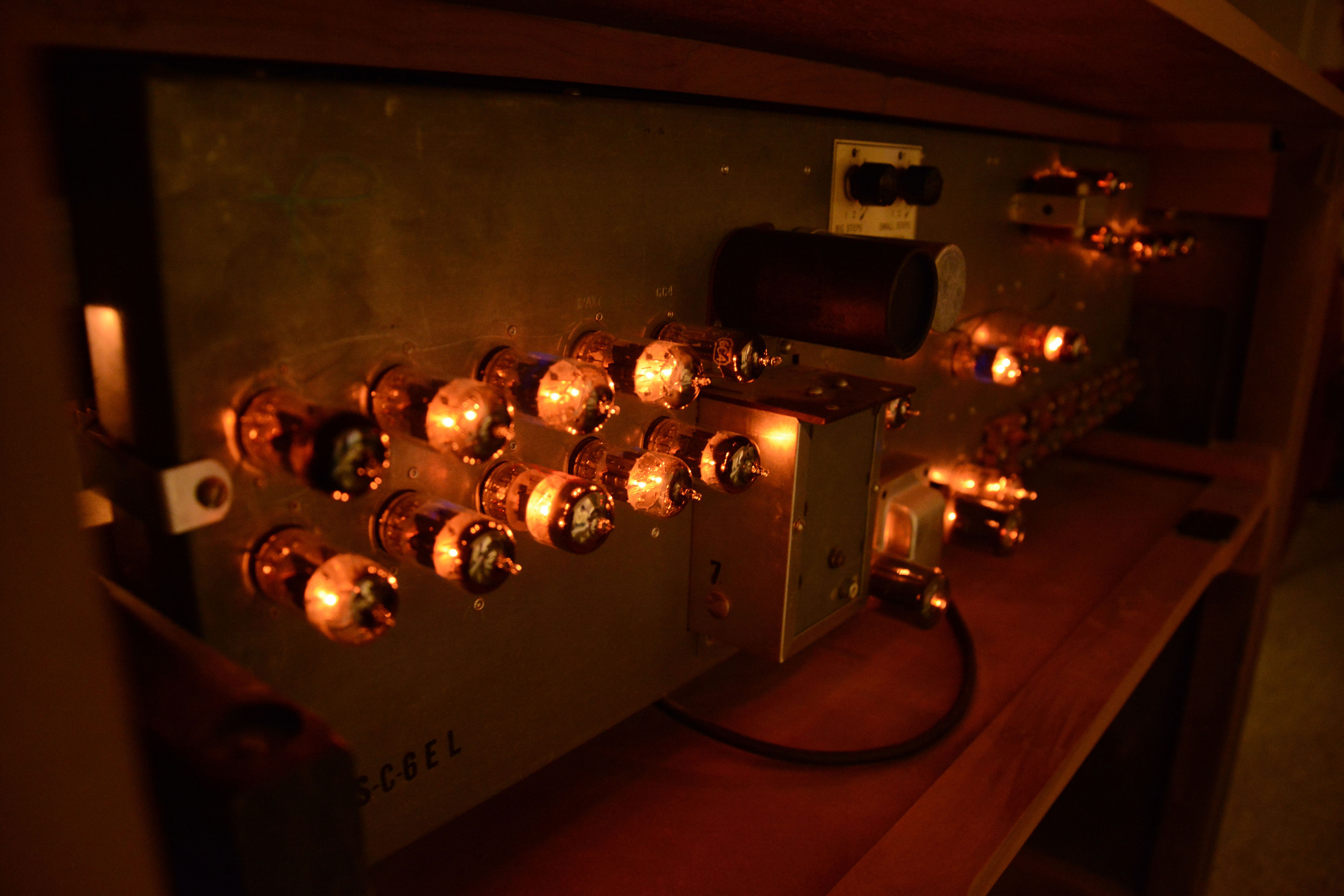
Now, don't worry too much if you haven't done this already. Hammond chord organs tend to be very reliable, with many still in playable condition with extremely few repairs (and no line fuse). In fact, as I will explain, my two units needed very little to bring them to the point of playing well, and neither have had fuse-blowing failures. Still, there is at least one story of a smoking S-6 (the one George Harrison used, no less), and one reader sent a picture of a burned-out resistor in the power section that probably resulted from a shorted filter capacitor. So, failures are known to occur—why not take a bit of effort to prevent damage when failure happens? Repairs of the 1956 "form B3" S-6This was my first S-6, purchased in June 2014. It was found at a thrift store called Castaways located in the small city of Lacombe, Alberta. I also found the extremely rare Kawai KMA-37 at this store 10 months earlier, and to this day, I periodically check it for keyboards. Anyway, coming upon this S-6 was the first I had seen or heard of a vacuum-tube organ. Never had I encountered anything with so many tubes before, and the build quality was obviously excellent, and the design beautiful. Although I normally don't apply power to tube electronics in unknown condition before inspection (and with a current-limited supply, etc.), I decided to try it out, and it worked well enough and with such a remarkable sound that I decided to buy it. Since it had just come in, the price was not set, and the storeowner had read online that it could be worth plenty, since she'd seen the "B3" on the builder's plate. However, after I explained that it wasn't one of Hammond's highly prized tonewheel organs, she decided to sell it for $60.00. It was then moved to the porch of my family's cabin at Gull Lake, where the pictures below were taken.
Although it had clearly been taken good care of, the instrument had multiple problems when received:
I will explain the solutions to these problems one by one. Firstly, the cause of the silent voices became apparent during tube testing: two of the 12AU7 tubes—the Solo Preamplifier/Pedal Control tube and the Pedal Divider Driver—each had one open heater, so these were replaced. This solved the solo and pedal problems respectively. The replaced tubes were original Sylvanias with green lettering. Secondly, when listening to the organ voice, the low B, C, and C# notes sounded noticeably quieter and duller than the others. Knowing that each organ oscillator is responsible for 2 or 3 notes, this clearly indicated a fault in one oscillator circuit. Based on page 22 of the service manual, the 3rd oscillator from the bottom is responsible for these three keys, which is the 2nd tube from the top of the organ chassis. Sure enough, it was another bad Sylvania 12AU7, which was weak in the corresponding section. This brings up a point: I encourage testing of every tube whenever you get a device in unknown condition. Even if it mostly works, this can reveal weak tubes responsible for slight worsening of performance, and tubes that have minor leakages before they can become major. However, especially the strength readings should be taken with a grain of salt; sometimes replacing a weak-testing tube will yield no practical improvements. Also, some basic checks can be done easily without a tube tester. For example, if your instrument has a dead function, first identify which tubes are related to that function (e.g. using page 21 of the service manual), then visually inspect each of these tubes to make sure all of the heaters are glowing. The 12AU7, 12AX7, and 12BH7 dual triodes should each have two heaters glowing inside, like so:
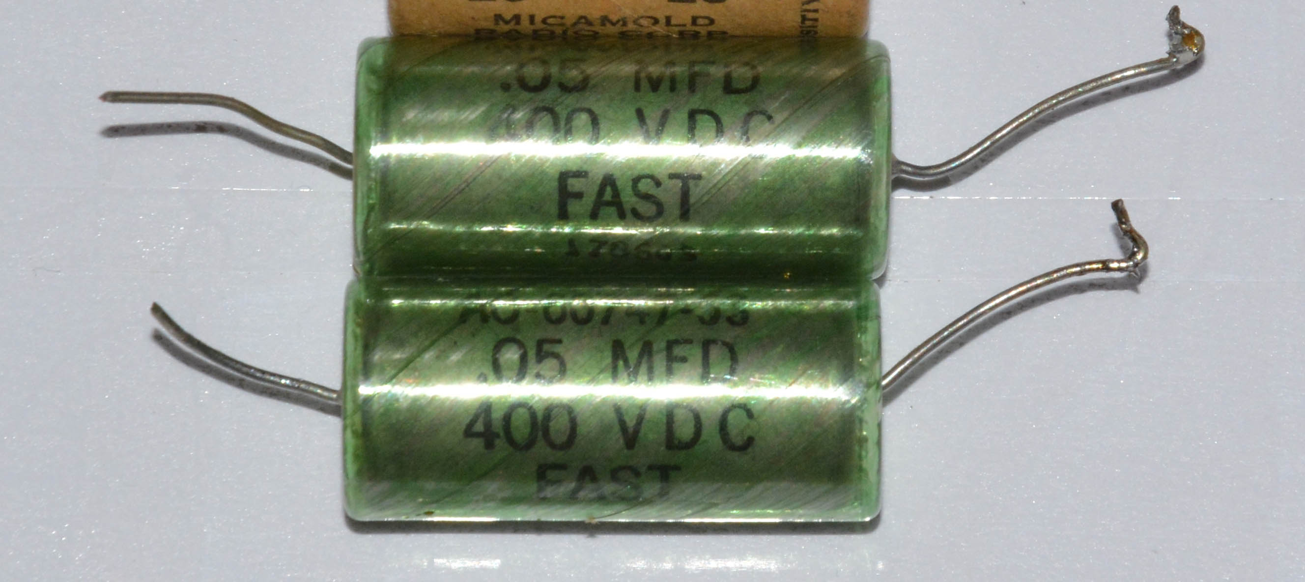
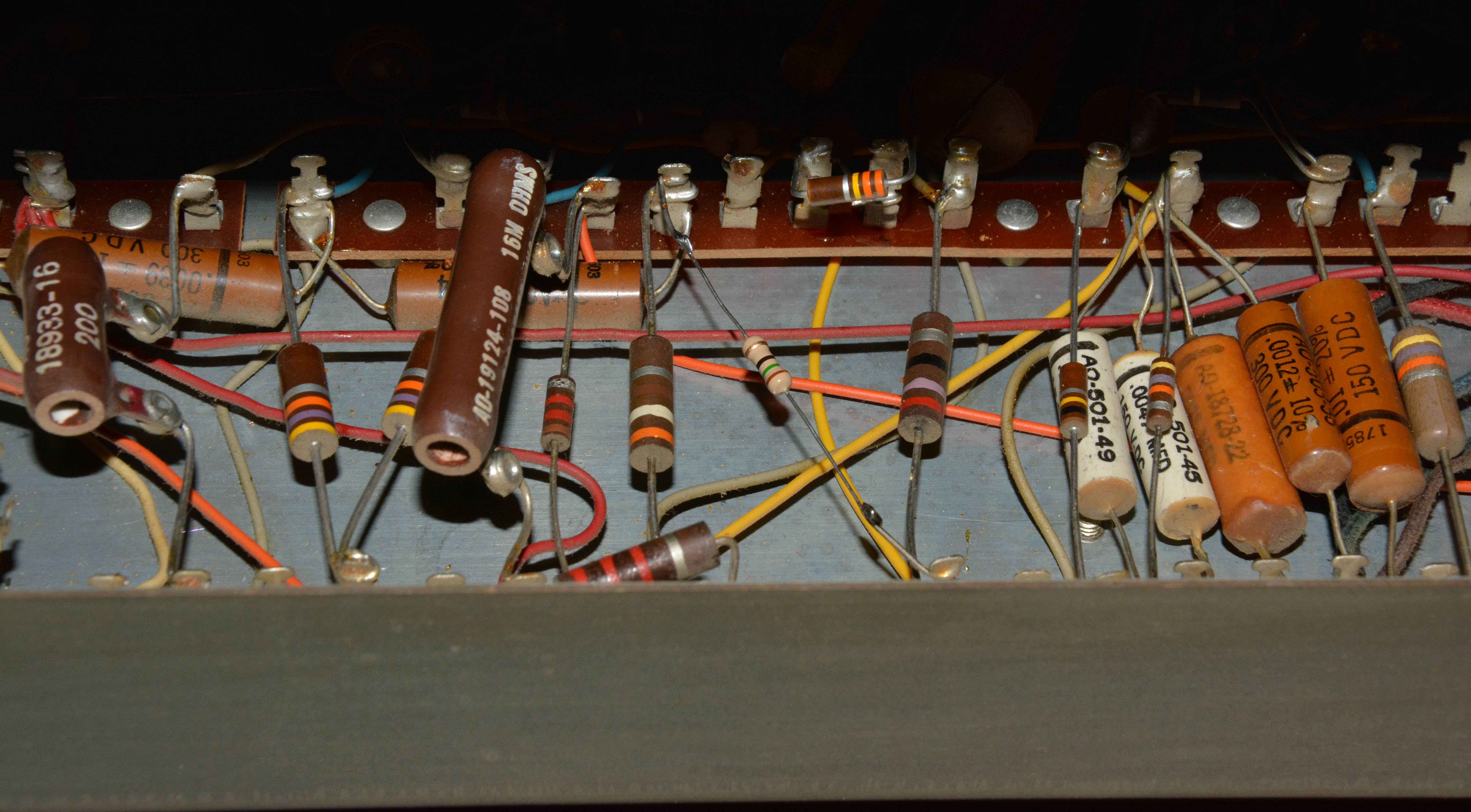
If a heater is not glowing, swap the tube with a new one, or with the same type taken from an unrelated working section. Procedures for determining which tube is faulty (on the model S) are described in the Owner's Service Suggestions manual, which also gives excellent tuning procedures for the organ and chord voices. Such tuning involves tapping the cores in and out of the oscillator inductors with a hammer and screwdriver. Not the easiest way to tune an organ, but not too difficult either. So far, all of the listed problems were caused by bad tubes. But like most electronics of its era, this S-6 also suffered problems caused by degradation of other components. Such a problem was the occasional quiet crackling noises in the speakers. Since the noise did not change with the expression control / knee lever, then based on the block diagram on page 13 of the manual, the suspect area narrowed down to either the power amplifier or power supply sections. In fact, the problem was caused by bad coupling capacitors between the 12AX7 phase-splitter and the two 6V6s in the power amp; these are C238 and C239 in the S-4 schematic, both 0.05µF at 400V.
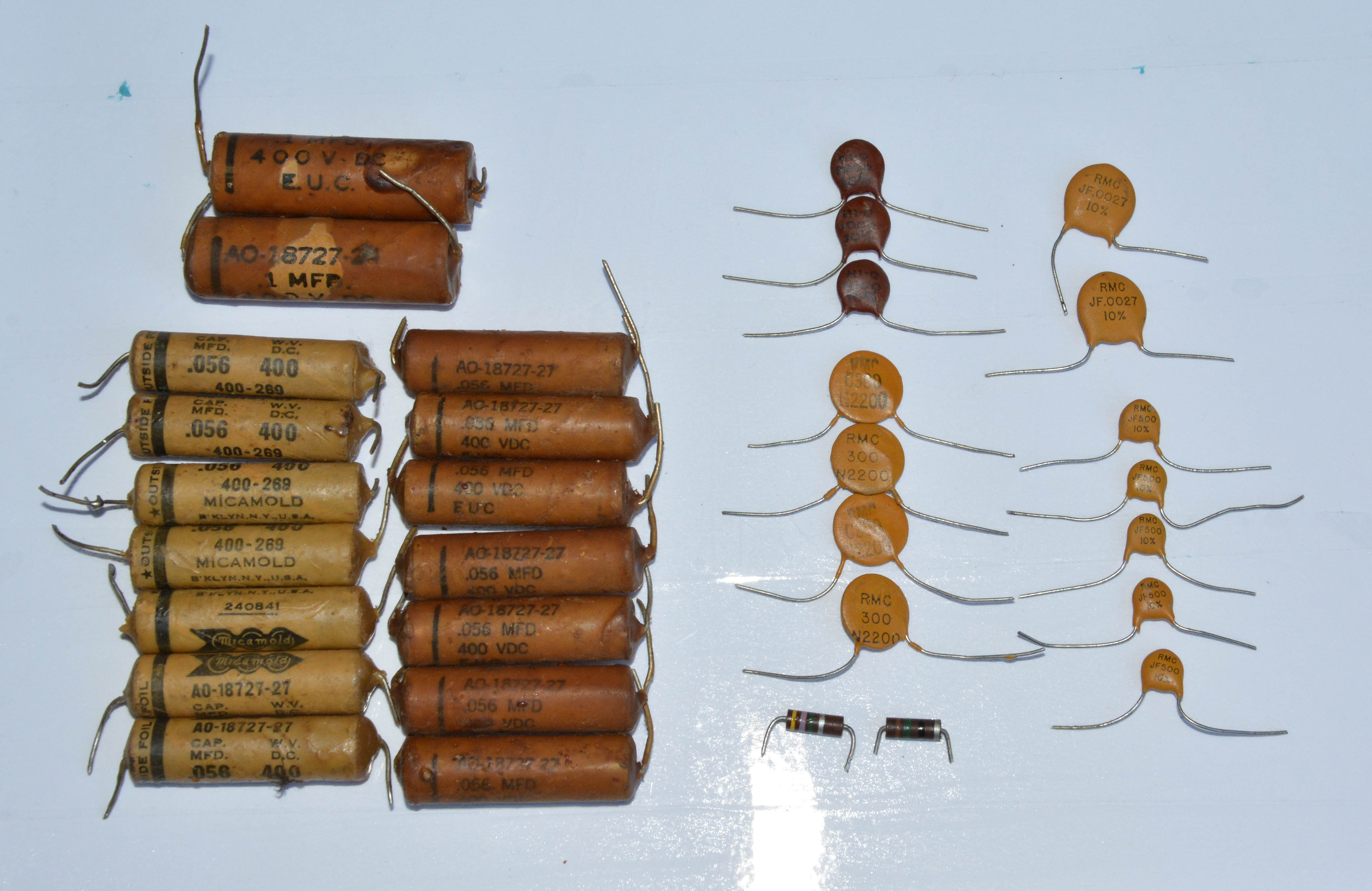
These are paper-in-oil capacitors, as evidenced by the metal body with rubber seals on both ends. Note the Hammond part number: AO-00747-53. Any caps in the AO-00747 series are paper, and paper capacitors are prone to developing electrical leakage, due to decomposition and moisture absorption of the paper. Sure enough, both measured electrically leaky on my Heathkit C-3 and Mr. Carlson capacitor testers. Replacing them with new 0.047µF film caps eliminated the crackling noise.
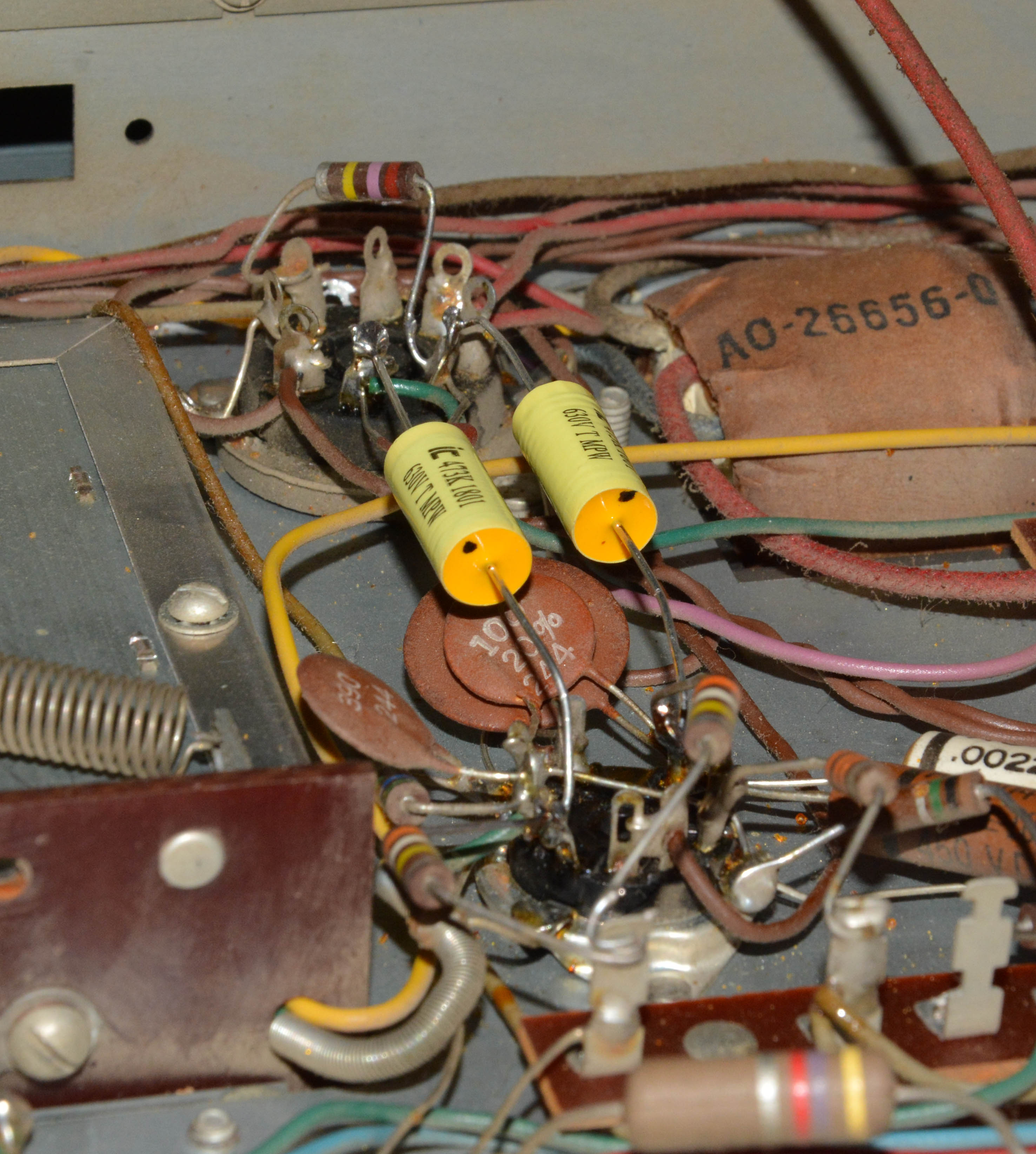
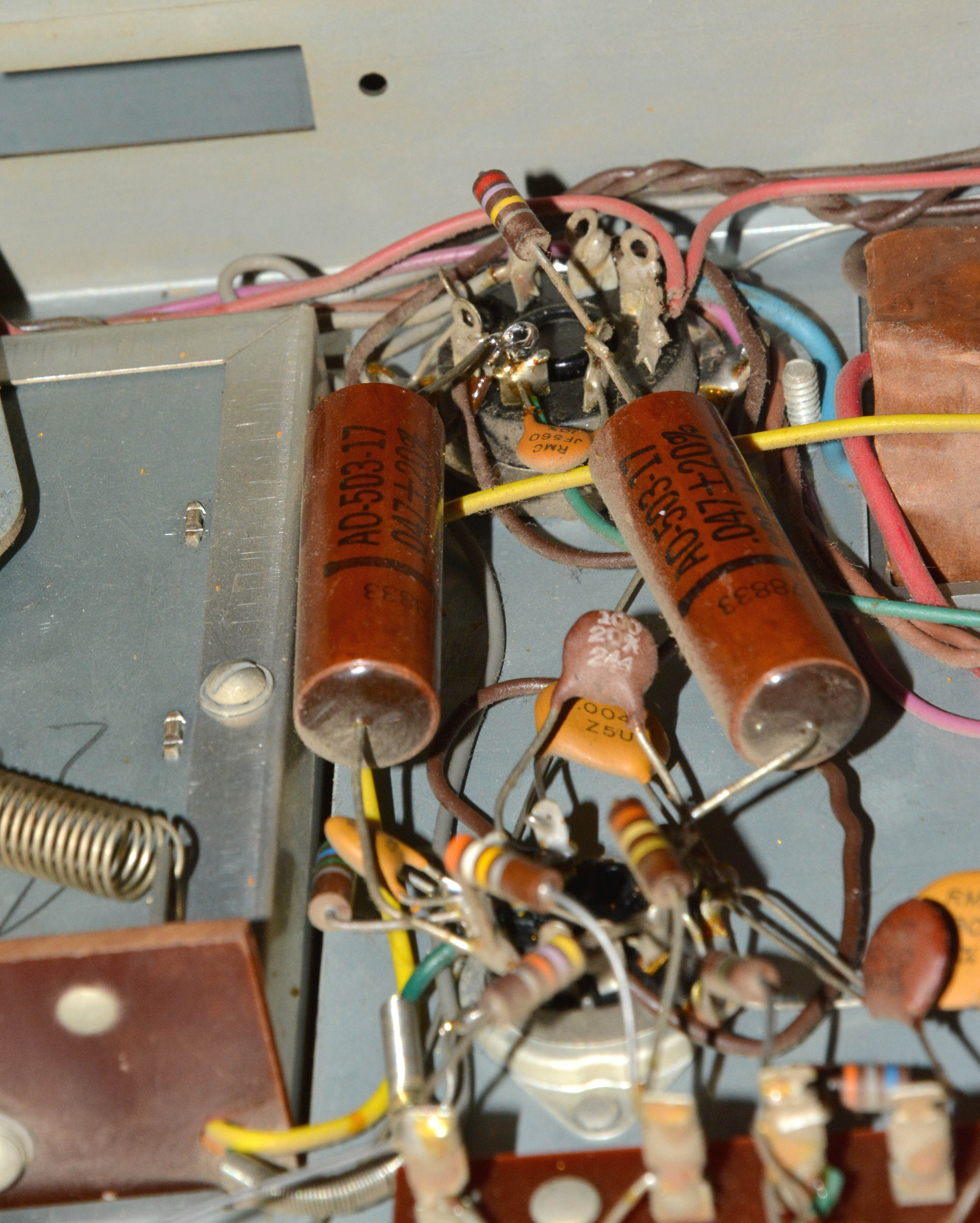
At this point, I should discuss "re-capping". In case you don't know, re-capping is the act of replacing every electrolytic and paper capacitor in something, in order to try to repair it, improve its performance, or just to reduce the chances of failure. While I agree that in some cases it is warranted, I decided not to recap either of my S-6s. First, let's talk about the paper caps... or are they? Most of the tubular capacitors in the S-6 are actually not paper, but plastic film. You can check the part numbers: from what I can tell, those with prefix AO-00747, AO-18727, or AO-18728 are paper, while those with prefix AO-500, AO-501 or AO-503 are plastic film. The paper types are encased either in metal cans with green or yellow plastic sheaths, or in wax-coated cardboard tubes. Plastic types are encased in either white ceramic or brown plastic tubes (the latter of which look similar to the cardboard-tube paper caps, but without the wax coating). You can also check with a leakage tester; I recommend building Mr. Carlson's 27-volt design on Patreon. Plastic capacitors should show no leakage whatsoever even on the most sensitive (i.e. "mica") setting, whereas even brand new paper capacitors usually show leakage on this setting. So, what about those capacitors that are paper? The two that I do recommend changing preemptively are the aforementioned coupling caps in the power amp. These are important, because if they short, the 6V6 power tubes will draw heavy current through the output transformer, possibly burning it out. Output transformers are difficult and expensive to replace. However, by 1958 when my form B unit was made, Hammond had already switched these capacitors over to plastic film, with part number AO-503-17 as shown below:
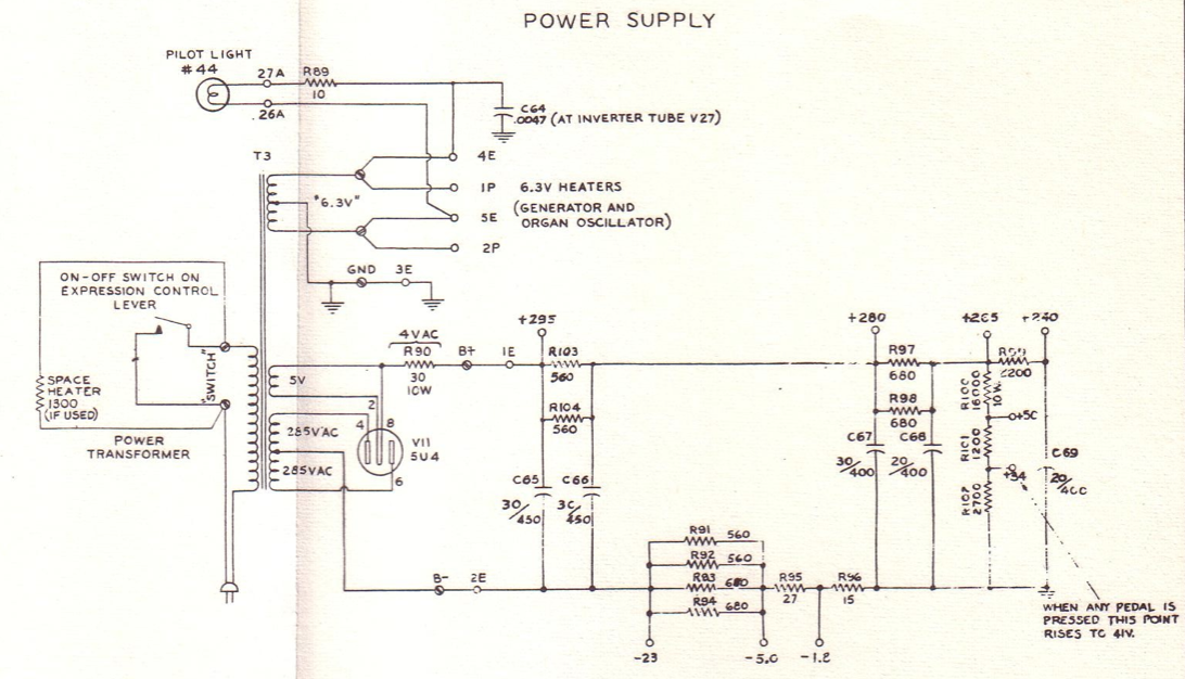
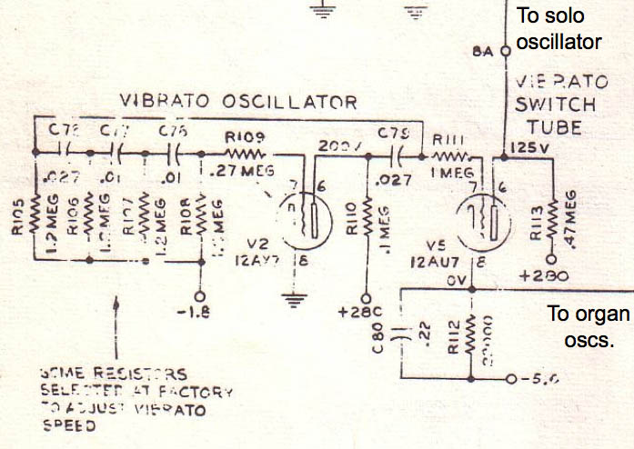
Plastic film capacitors should not be subject to re-capping, because they are extremely reliable. As well, it would not be easy to bulk-replace all those in a Hammond chord organ, since many of them were individually chosen at the factory for proper tuning, and with strange values such as 0.167µF and 0.0882µF. Bulk replacement, unless done very carefully, would ruin the tuning, besides having virtually no benefit. In any case, the rest of the paper caps aren't cause for much concern. If they short, they might cause a fried resistor at most, but that's an easy and cheap replacement. Some don't even have DC voltage across them, such as those in the solo timbre filters. I did try to replace the various paper caps on the organ chassis of my form B unit, which I'll discuss in the next section. As for the electrolytics, the reason I haven't bulk-replaced them is because, well, they show no signs of problems. There is no filter hum in the audio, no electrolyte leakage, and the cans aren't getting warm to the touch even after hours of operation. Because I installed a fuse, it should prevent the power transformer from toasting if a filter cap shorts, and the only other components that may get fried are some easily-replaced resistors. Note that the situation is slightly different on the model S and S-1, since the speaker's field coil is part of the power supply. But overall, I don't consider it necessary to replace the electrolytics. Once one fails, sure, I might take the opportunity to change them all, but until then, I'll be continuing to enjoy the remarkable quality of these over-60-year-old parts. Returning to the problems, another one was weak vibrato, especially on the organ voice. Below left is the vibrato circuit, and right is the power supply.
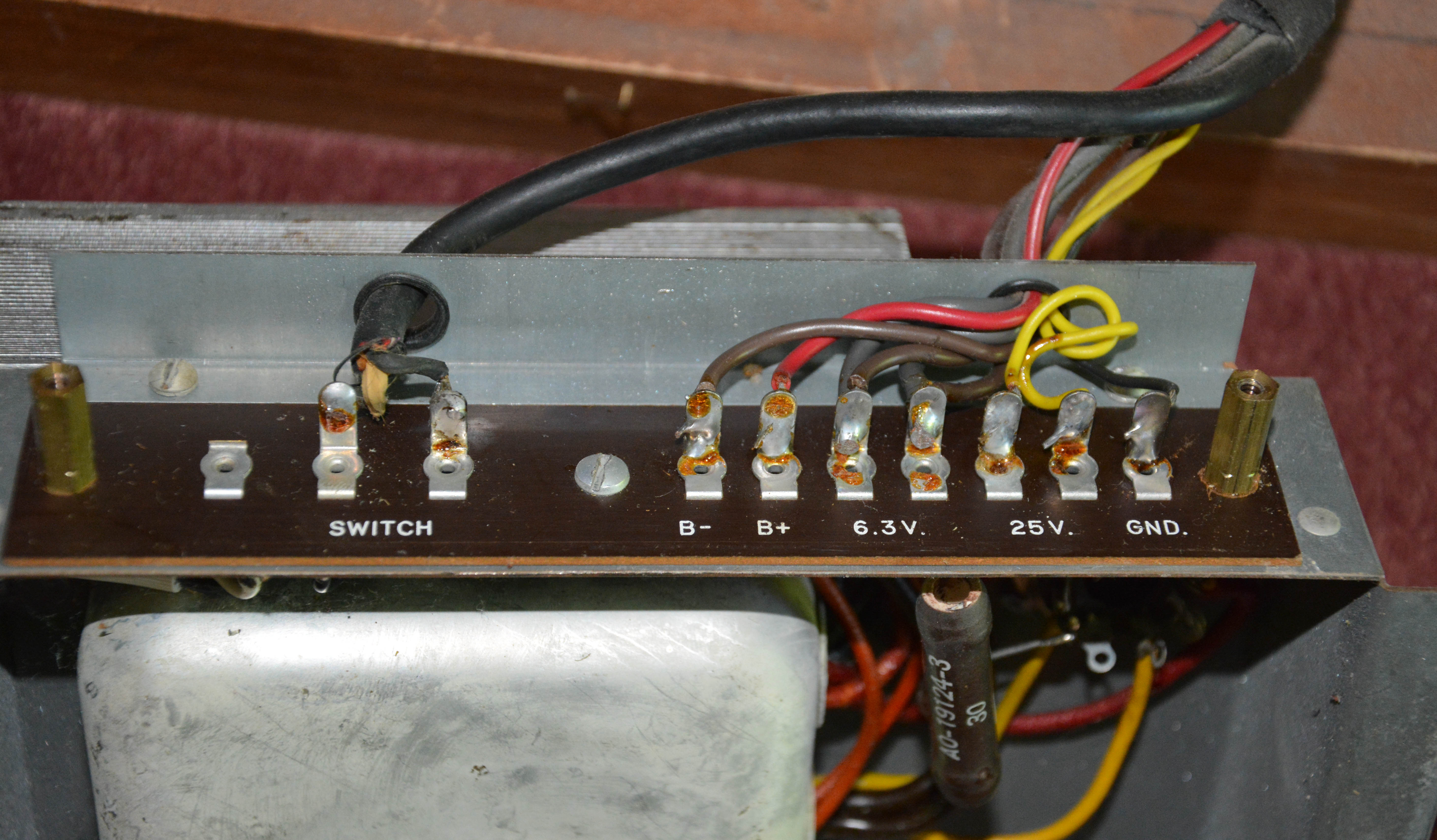
Measuring the plate of V2 with an oscilloscope, I found that the vibrato oscillator was indeed oscillating, and with plenty of amplitude. However, looking at V5, the "vibrato switch tube" (which actually performs no switching, rather acting as an amplifier and buffer preceding the switches), the cathode voltage was significantly lower than 0V. Since this voltage is dependent on the negative bias voltages from the power supply, I measured those, and found them too negative. Then, testing the resistors in the negative supply, I found that R96 (the 15Ω 0.5W resistor providing the -1.8V bias) measured about 30Ω! Replacing that, the bias voltages were correct once again, and the vibrato was significantly deeper. This same resistor had also drifted (to a lesser extent) on my form B S-6, so it's worth checking. Don't replace it with a higher power than 1/2W, since that will reduce its fusing effectiveness in the case of a filter cap short.
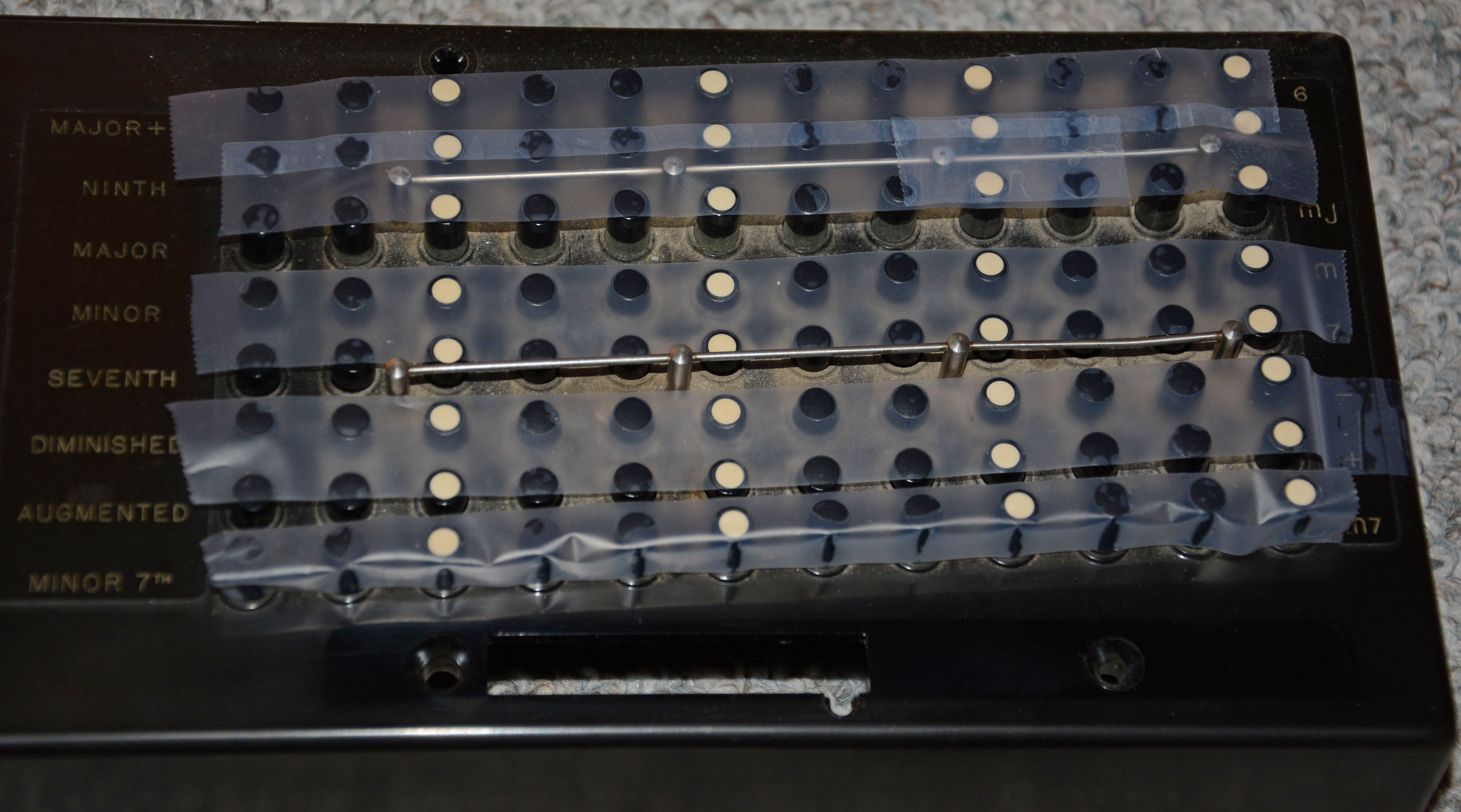
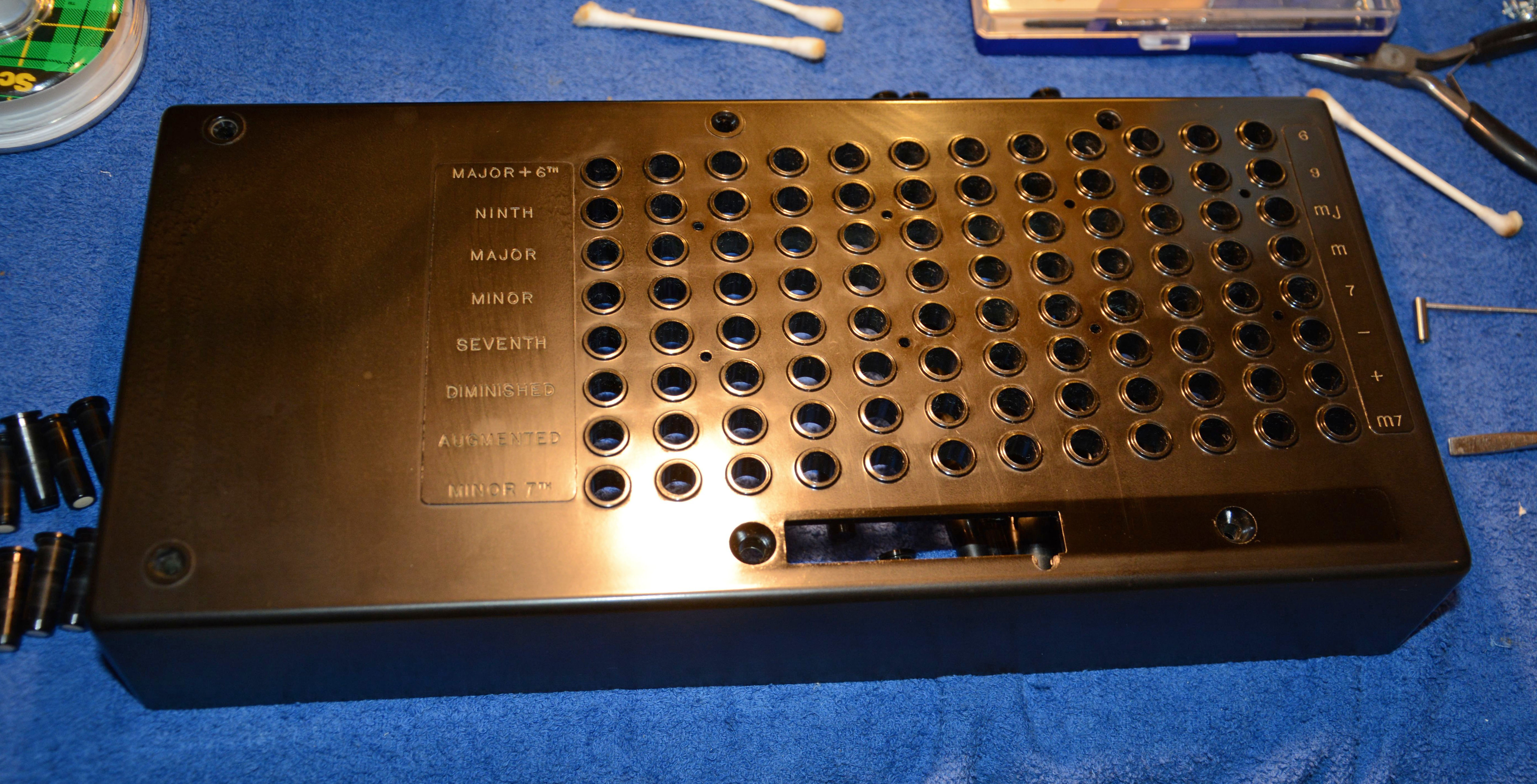
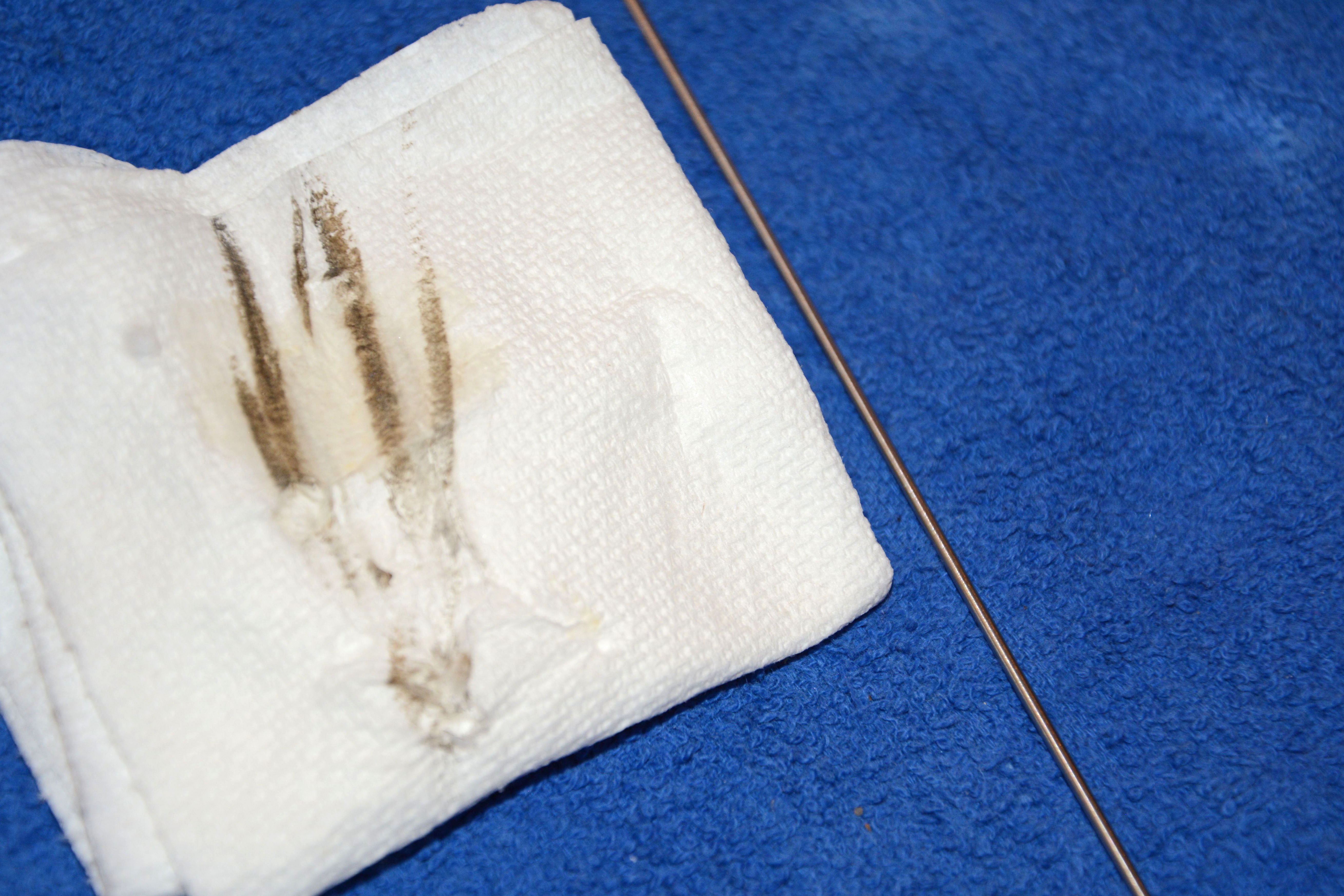
Of course, I also installed a 1.5A slow-blow fuse in an inline holder. I also replaced the decayed rubber power plug, and noticed that one of the wires in the power cord was decomposed and cracking, while the other was still flexible. At some point I will deal with that... Now we will get into mechanical problems. The first was that the movement of many of the plastic "control tablets" was stiff. It is difficult to know how best to lubricate plastics, but my method has been effective so far, and hopefully will not have long-term negative effects. I used MG Chemicals' Contact Cleaner with Silicone, applying a small amount at each of the pivot points (which are accessible after removing the top wood panel by means of two bolts). The solvents of the contact cleaner quickly evaporated, and a thin layer of dry silicone was deposited in each bushing, making the tablets rock back-and-forth smoothly once more. Again, I don't know what long-term effects the dry silicone may have on the plastic, if any, but what I can say is that the tablets have continued rocking perfectly for the last 5 years since I applied the lubrication. In June 2015, I cleaned the chord buttons and their associated panel, since especially the area between buttons was thickly coated with a sticky "nicotine" film. The process to remove these pieces is as follows. Firstly, adhesive tape must be applied across all of the tops of the chord buttons, otherwise they will fall out when the plastic panel is lifted. Then, the thin plastic strip with the chord names (C, G, etc.) has to be removed by some small flat-head screws. Next, the chord bar must be removed, first by removing the two screws holding it in place, and then by removing the single screw holding its switch to the chord bar; the service manual says to desolder this switch, but this is unnecessary as long as you keep its pieces held together (e.g. with tape) while the screw is removed. Finally, the remaining four screws can be removed and the chord switch cover lifted off. Here are some images of the condition before cleaning:
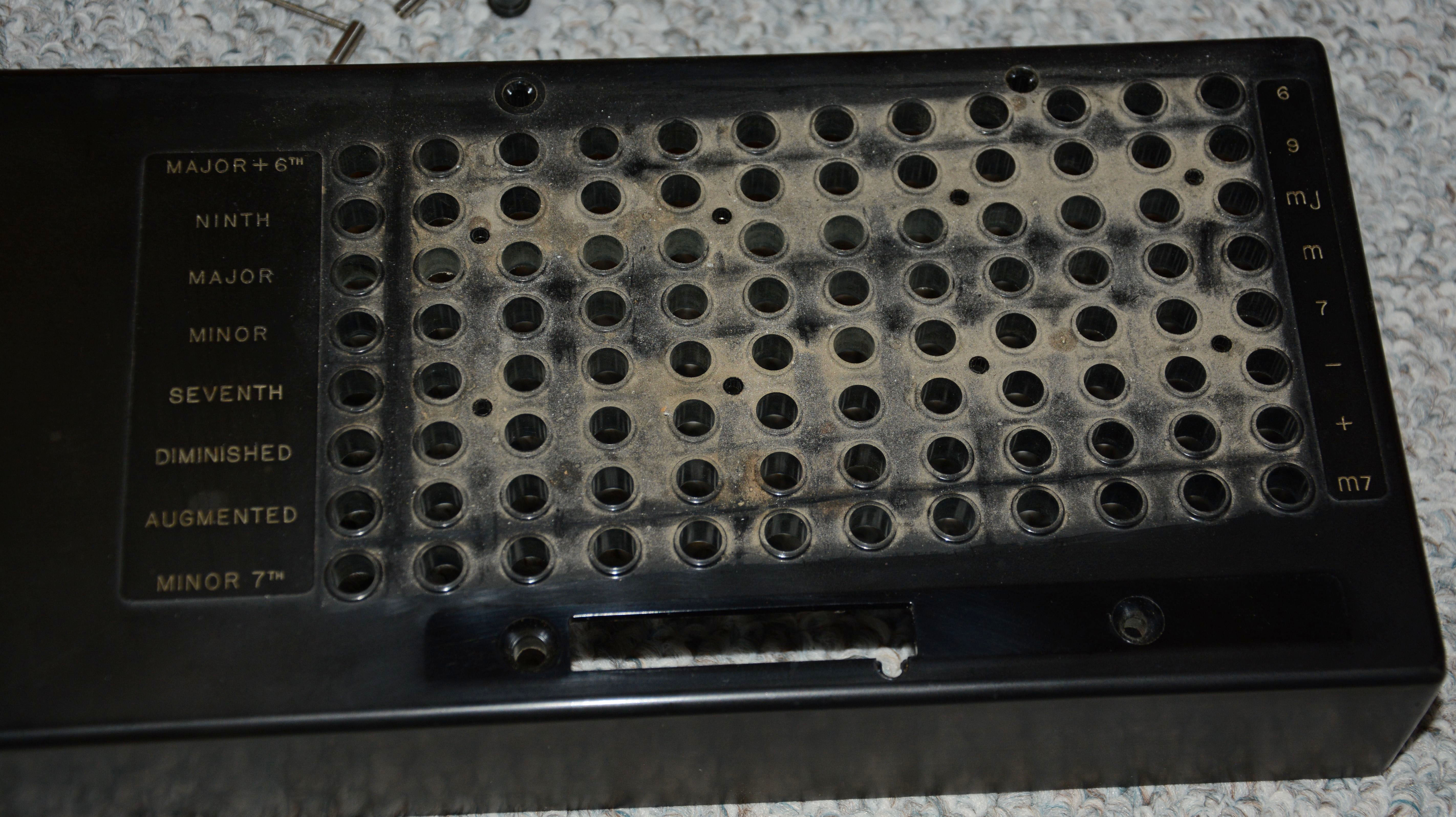
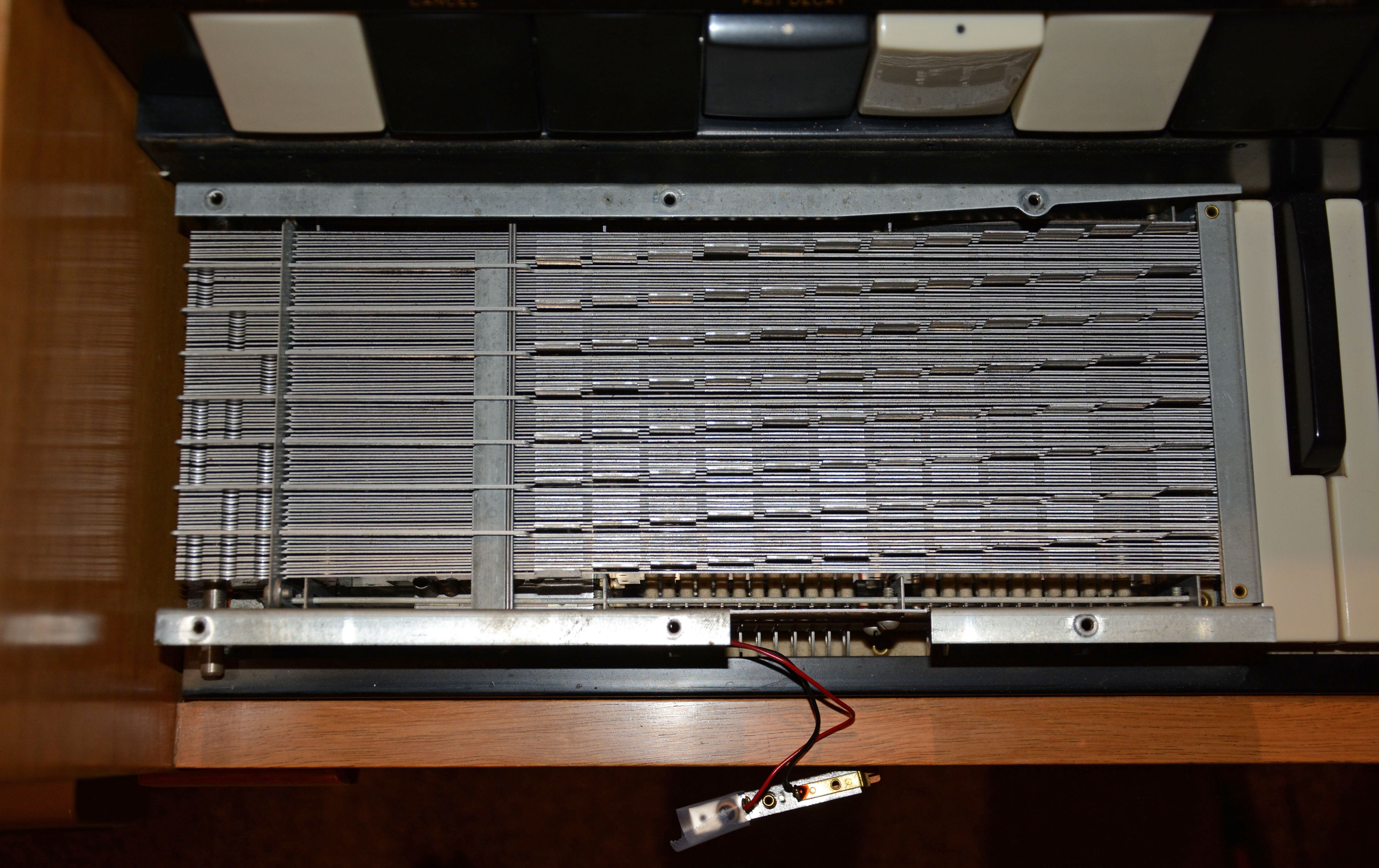
When cleaning the chord buttons, the chord switch cover holding them must be removed, which reveals the array of 96 thin metal plates, each corresponding to a chord button. These make the necessary contacts for each button, and are impressive to look at, being yet another beautiful and enduring long-lost technology, perhaps never to be seen again.
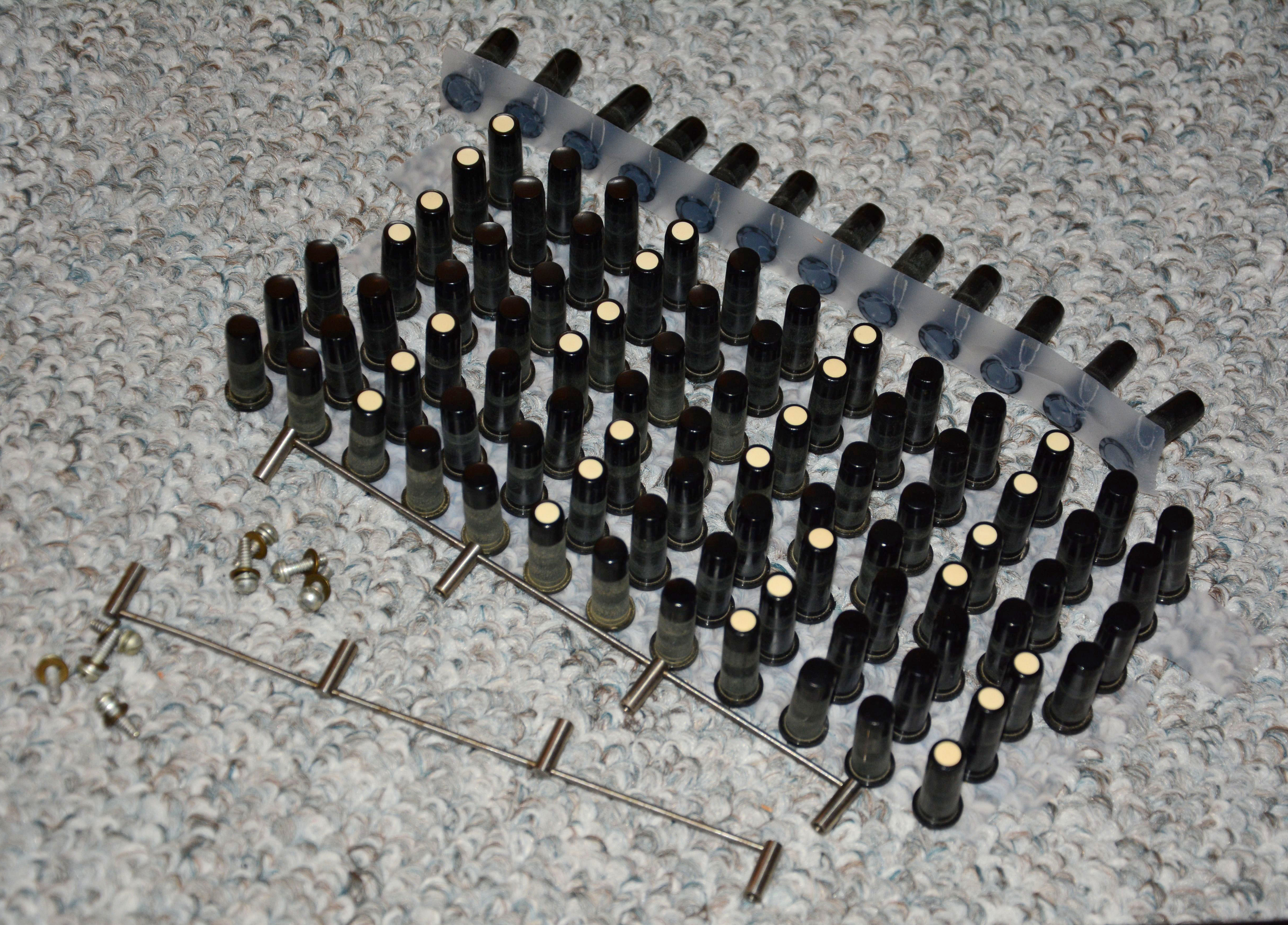
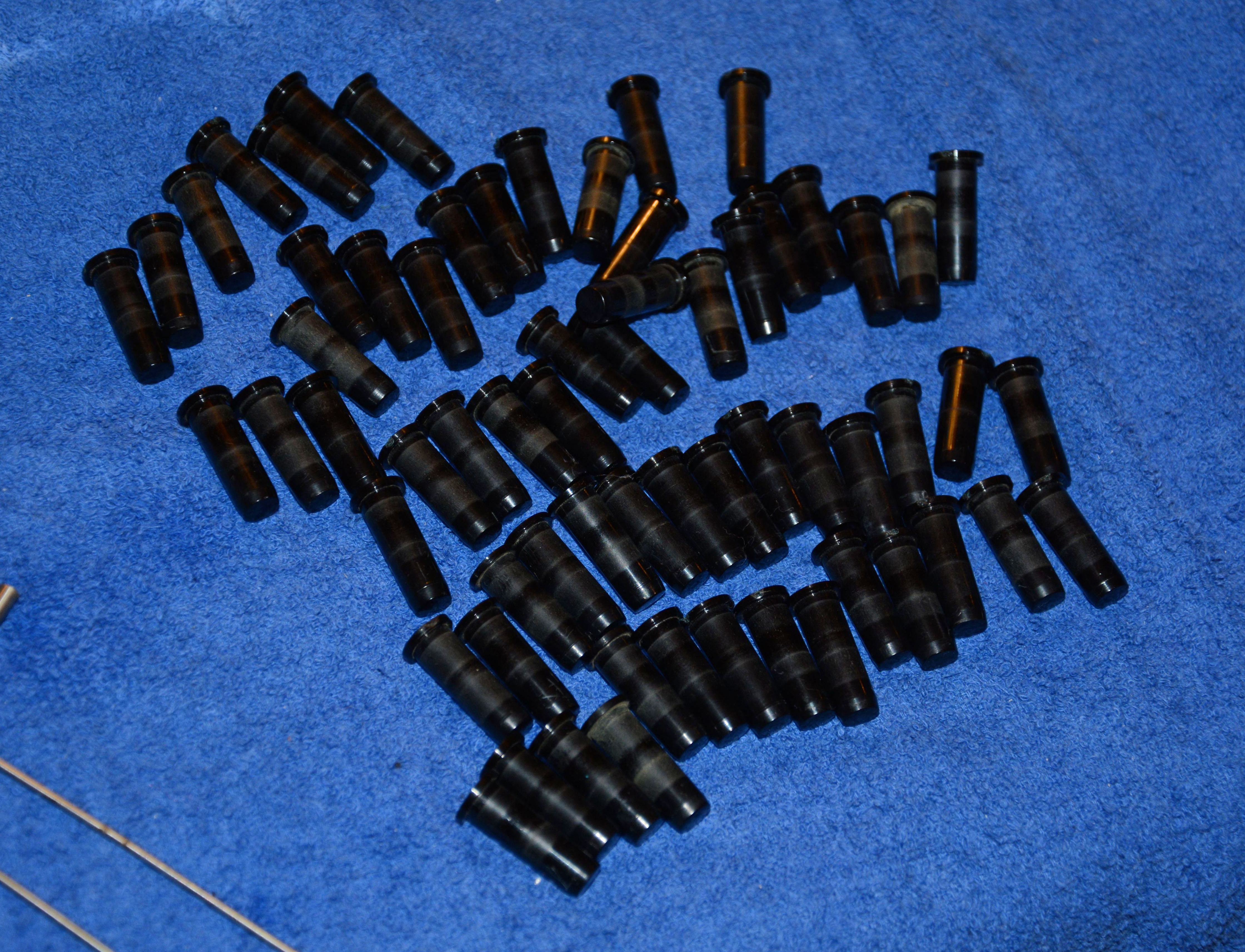
The chord switch cover was cleaned mostly in a large sink with a cloth soaked in soapy water. Unscented hand soap was used. After being run under tap water to wash off soap, the remaining dirt was then removed with moistened cotton swabs. The chord buttons were placed into a tub full of soapy water and individually scrubbed, then placed in a tub of plain water to remove the soap, and then left to dry. As well, the metal hardware was cleaned and polished using Brasso. It all turned out quite well, and this concludes the repair of the "form B3" S-6:
Some various pictures are shown below:
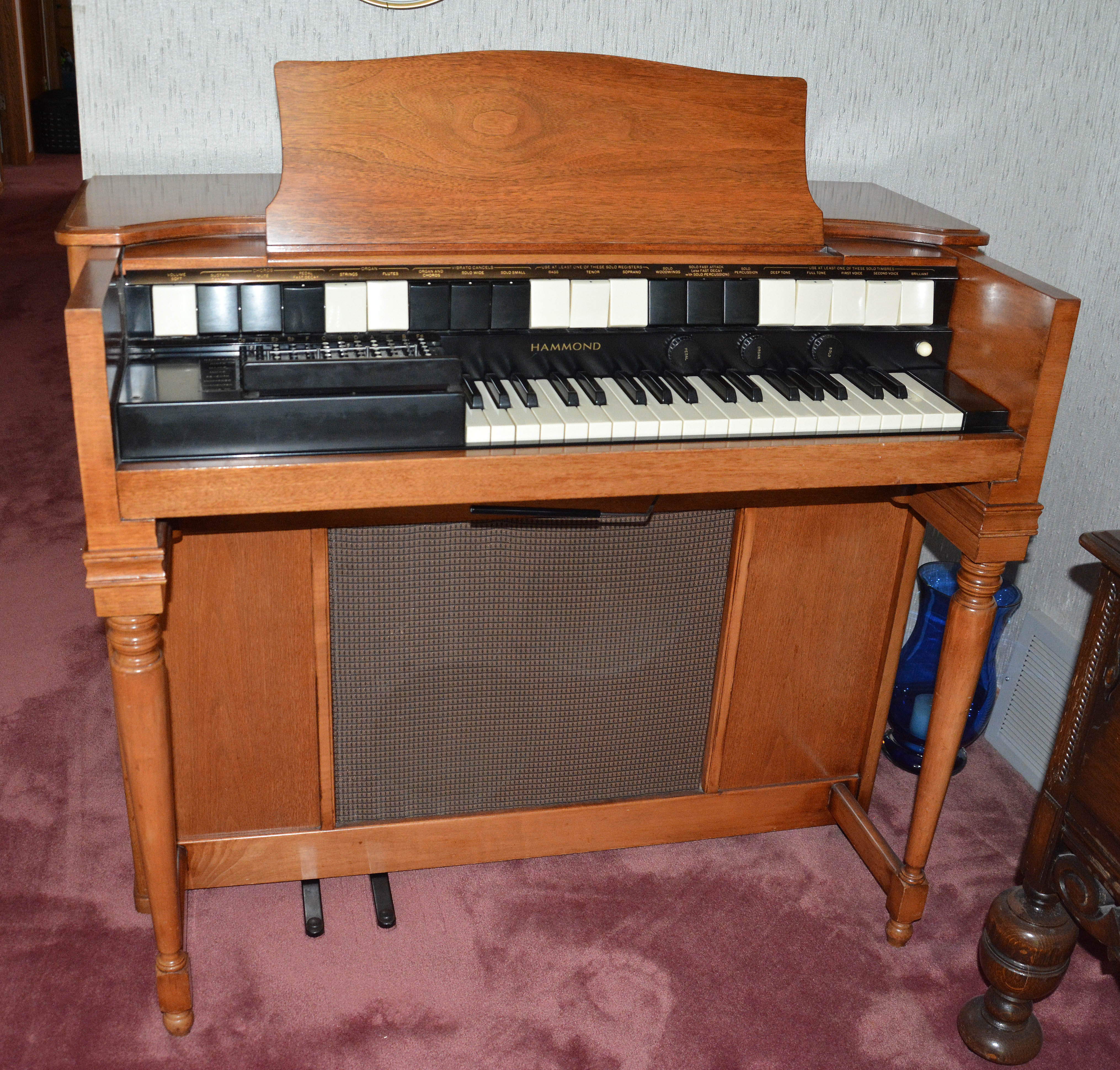
Repairs of the 1958 "form B" S-6I received a second S-6 in September 2017 from my good friend Isaac, who got it for free via a local Kijiji listing. It was given away by the family of a recently deceased elderly woman, who had been its only owner unto that time. Based on tube dates, it was made in 1958, so just imagine that... owning and playing a fine electronic instrument for 59 years! This S-6 is form B, and as compared to the form B3, it has has a darker stain to the wood, as well as slightly more ornate woodwork.
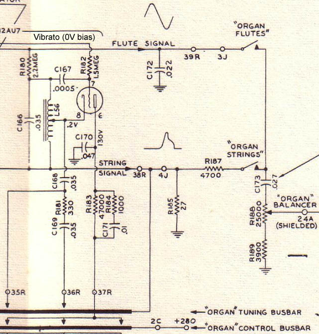
It has some minor differences in the layout of components in the generator chassis, as well as a higher proportion of plastic-film capacitors as compared to the 1956 form B3. However, all of the tubes are the same, and overall, the sound is nearly indistinguishable from the B3 besides having faster and deeper vibrato. Like the B3, this instrument had been well cared for. Every function essentially worked to begin with. Only after spending time with it did I notice some faults. Some notes of the organ voice had extremely deep vibrato, and some notes of the organ oscillators were unable to be brought into acceptable tune without detuning the other note(s) of the same oscillator. Both of these issues turned out to have the same root cause. Below shows one of the organ oscillator circuits. Considering the aforementioned issues, what components are likely to be at fault?
One obvious possibility is R182 drifting low in resistance, since it provides the vibrato signal to the grid of the oscillator tube. But no, that was not the issue. Without further ado, the problem was the ceramic "coupling" capacitor to the grid, C167 in this oscillator. Upon measuring, I found that many of these ceramic capacitors had drifted low in capacitance, causing both the strong vibrato and improper tuning interval problems. The vibrato is easy to explain, since a lower value of C167 results in a higher amplitude of vibrato signal at the grid. It is harder to explain how it causes a tuning interval problem, so I will leave it to you to figure out. There are five values of these capacitors: 300, 500, 1000, 2700, and 3300 picofarads. The smallest are too small to be measured adequately on all of my digital meters, so I tested with a period-correct Heathkit C-3 "Condenser Checker". The worst were certain 500pF parts marked "RMC" (a Mallory series, apparently). All of them were slightly low, including some dark red ones not marked RMC, so I decided to replace all except the 3300pFs with silver mica and polypropylene parts (and a few "normal" ceramics). Below left shows the finished organ chassis, and right shows the parts replaced.
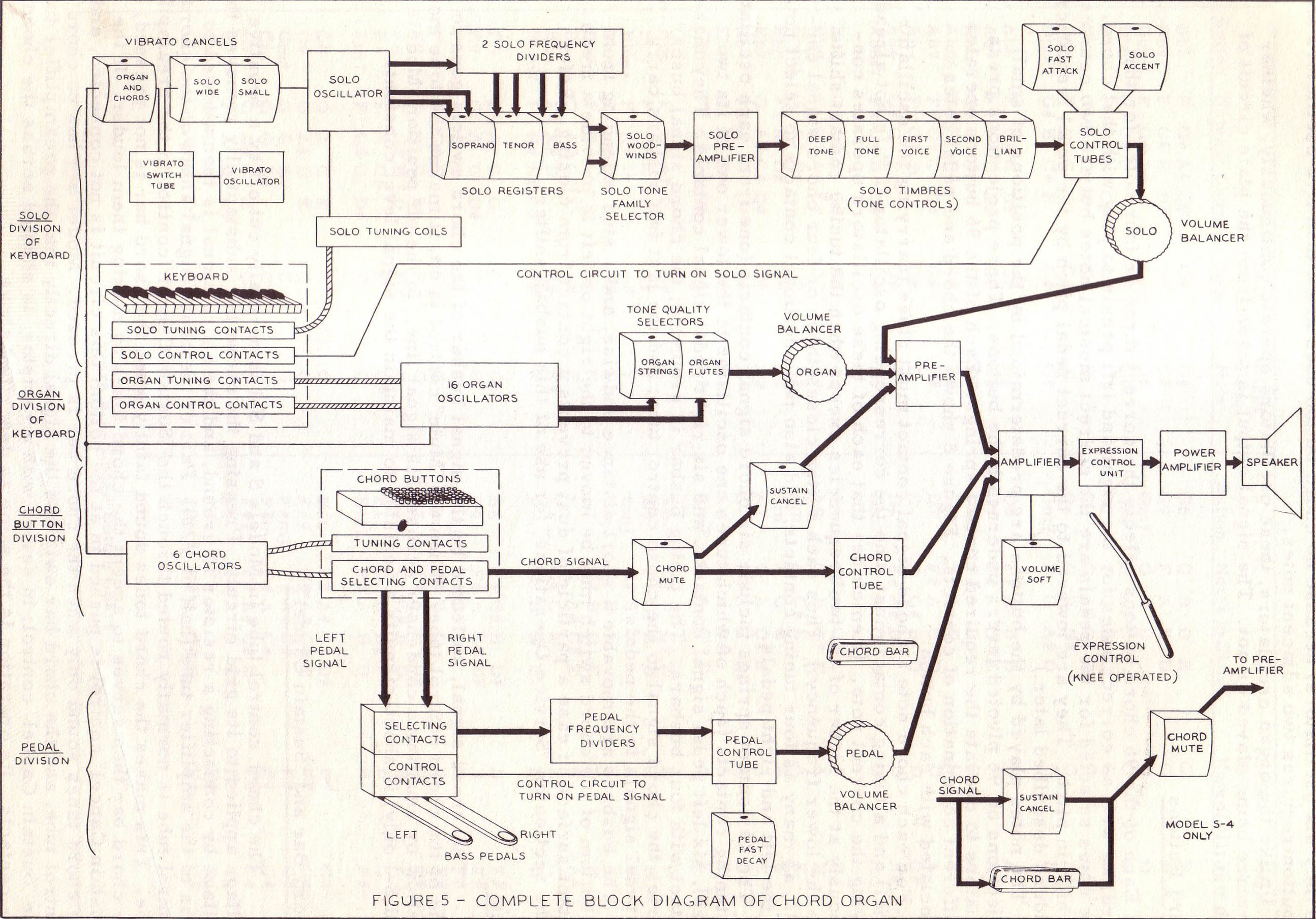
I also replaced a few out-of-tolerance resistors and all of the 0.056 and 0.1µF paper capacitors. I figured it was a good idea, since the paper caps measured rather leaky. Since 0.056µF capacitors are not so common now (especially in axial form), I used 0.047µF, which happens to be the value specified in the S-6 schematic. My form B3 uses 0.05µF caps in this position. It is really not a critical value, as evident by the jump from 0.047µF to 0.1µF for the two lowest oscillators! After doing all of this, and tuning the organ oscillators via the inductor cores, all was well in the organ division. Besides installing a line fuse as described earlier, I haven't performed other work on this instrument. The vibrato is a bit fast for my tastes (and still rather deep, which would probably be remedied by slowing it down), but none of the parts in the vibrato circuit are out of spec, so I have left it as-is. Thus concludes the repairs of the Form B S-6. The Electronic DesignI will explain here some sections of the electronics, especially for the benefit of those who are, like me, interested in making tube-based musical instruments. Most analysis will be done on the S-4's schematics, since they are better-scanned than those of the S-6 and mostly the same, but some comparisons will be done where differences exist. There are already some good descriptions in the excellent service manual, but they don't go into fine detail, nor into the types of information useful for making design choices, and they of course don't relate the concepts to more recent synthesizer terms. So, first, have a look at the block diagram from page 13 of the manual:
With that in mind, and referring back to it whenever you feel necessary, let's start by looking at the vibrato oscillator circuit, which provides a low-frequency sine signal to all three divisions of the instrument:
This is a conventional phase-shift oscillator. In such, the output of an amplifier is fed back to its input through multiple passive filter stages. These stages effect a frequency-dependent phase shift on the signal, such that at one particular frequency, the phase shift between output and input is exactly 180º. Since the amplifier inverts the signal (equivalent to a 180º phase shift for all frequencies), the result is a 360º shift, i.e. positive feedback, and hence oscillation, so long as the amplifier's gain is high enough. Since each filter stage has a maximum phase shift of 90º, at least two stages must be used; in practice it is always three or four. In this circuit, V2 is the amplifying element (note that a 12AX7 is used instead of the lower-gain 12AU7 used for most other purposes), and there are four passive high-pass filters comprised of 0.027µF or 0.1µF capacitors and 1.2MΩ resistors. The oscillation frequency is approximately 6 cycles per second. Phase-shift oscillators are by far the most common type used for vibrato and tremolo in vintage organs and amplifiers. Yet, they are almost never used for audio generation—why? Because they are more complex and unstable than the L-C oscillators of their era. They require at least three pairs of resistors and capacitors for the frequency-selecting elements, while all that's required for an L-C is an inductor and a capacitor. Also, since the frequency depends on R-C time constants, the effective plate resistance of the tube affects the frequency, and this changes with age. Carbon-composition resistors and paper-dielectric capacitors also drift significantly with temperature and humidity. In an L-C oscillator, just the single capacitor is of concern, since the inductor usually has very low drift. Also, a phase-shift oscillator's frequency cannot be voltage-controlled, because the frequency response of the filters depends only on the component values. Phase can be controlled somewhat, e.g. by varying the grid voltage; this can add vibrato to an audio phase-shift oscillator, the same way as done with L-C oscillators. But in almost all cases, a VCO is a type of relaxation oscillator, where frequency depends both on component values and voltages. It is possible to make such oscillators with vacuum tubes, thyratrons, or gas-discharge lamps, but don't forget to use a regulated power supply to maintain stability. L-C and phase-shift oscillators have the benefit of not requiring a regulated supply. Anyway, that is enough about oscillator types for now; some day I hope to make a good list of analog oscillators suitable for musical purposes, but until then, back to the S-6! Now, let's look at one of the organ oscillators, in this case the highest one:
Well, it's a Hartley oscillator, but with some additional circuitry to facilitate: generation of three possible frequencies, modulating the frequency with the vibrato signal, powering and unpowering the oscillator, and outputting two timbres. The basic oscillator is comprised of a 12AU7 triode, grid-coupling capacitor C167, plate components (R183, R184, C171), and of course the tank circuit formed by inductor L56 and capacitor C166. How does a Hartley oscillator work? I've never found a great explanation, so I'll try to write one now. First I'll explain how a capacitor-inductor "tank" is resonant. This is because both elements store energy, but one stores it in an electric field, and the other in a magnetic field. To sustain an electric field requires constant voltage, whereas to sustain a magnetic field requires constant current. Considering also that capacitors resist change of voltage, while inductors resist change in current, it follows that the energy will flow alternately between elements, resulting in resonance at a frequency determined by the inductance and capacitance. To illustrate, let's say you charge a capacitor to an arbitrary voltage, then connect it across an inductor; in this circuit, there is only one voltage, and one current path. Current starts at zero, and gradually starts to flow, until all energy has transferred from the capacitor to the inductor. Now the voltage is zero, but current is still flowing. This current flows into the capacitor, causing the voltage to increase, this time in opposite polarity. Eventually, the capacitor is fully charged; current is zero, and voltage is the same as initially, but opposite polarity. Thus completes one half-cycle, and I'm sure you can extrapolate the rest of the cycle. If the elements had no losses, this could go on forever. Of course, because all real components have losses, the tank must be re-energized to sustain oscillation. This is the tube's main purpose. Let's say that at a particular instant, the node of R180, C166, C167, etc. is positive in voltage and rising. C166 must therefore be charging from the energy leaving L56. The aforementioned node voltage is rising faster than the cathode voltage (since L56's tap acts as a simple voltage divider), but is in phase with it. The tube's grid voltage is also rising (since it is coupled to the tank through C167), and as it rises with respect to the cathode, the tube's current increases, energizing L56 via the tap, causing the voltage to increase even more (by autotransformer action), until eventually the grid conducts current, removing some energy from the circuit, and resulting in no further increase in cathode current. Shortly thereafter, the inductor has no additional energy to transfer to the capacitor, and the voltage decreases. On the negative half-cycle, the grid has a negative peak relative to the cathode, so the tube is cut-off. Thus, re-energizing only happens on the positive portion of the cycle.
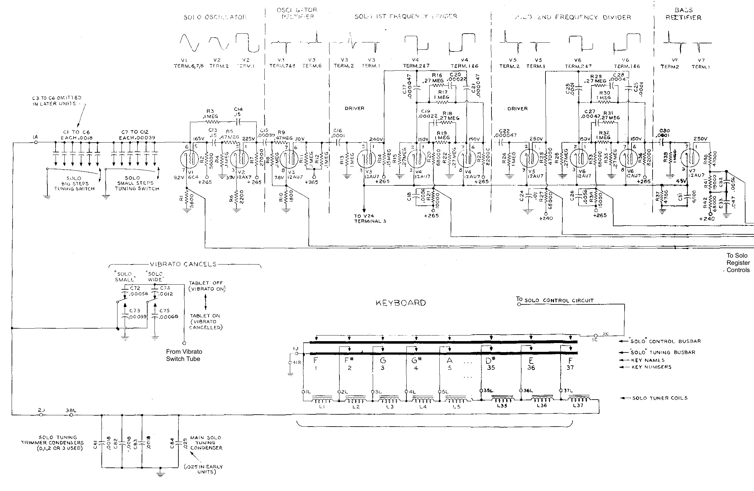
Output is taken from two different points. Firstly, considering the signal across the tank is a nearly pure sinusoid, it makes a good candidate for a mellow "flute" stop. Thus, it is summed to the Flute Signal bus via a large isolating resistor. For the Organ Strings bus, the lower nodes of the tanks are all connected together, then grounded through a very small resistor, R185, across which the signal develops. Because the tubes only conduct on the positive half-cycles, this signal is quite harmonically rich, similar to orchestral strings. The voltage waveform that develops is not a conventional type, being a kind of lumpy pulse-wave; its approximate shape is drawn on the schematic. This is one reason why these tube organs sound unique—you could even call it the "Hartley sound"! Such a design was also used in certain Conn organs, including the "Artist" 700 described in Richard Dorf's Electronic Musical Instruments, 2nd Edition, which even uses the same 27Ω resistor value for its string bus. Note also the plate circuit. R184 and C171 are used to provide a faster attack by charging C170 with higher initial current. Bypass capacitor C170 makes the plate voltage reasonably constant, which increases the grid voltage's effect on cathode current (though this is not really necessary, as evidenced by the design of the chord oscillators). Plate voltage is only applied when a key is pressed, therefore the organ oscillators are normally silent. Thus, they can remain coupled into the audio signal path at all times. Conversely, the chord, solo, and vibrato oscillators run constantly. However, the chord oscillator signals are only coupled to the audio path (and the pedal dividers) when buttons are pressed, meaning they are practically as silent as the organ oscillators when unplayed. Even with the knee lever wide open, very little noise is heard without playing—just the slightest hint of the solo voice. The chord organ is really a remarkably low-noise instrument; certainly better than many divider-type organs, besides plenty of digital keyboards! How does the vibrato work? First, note that the vibrato line is connected to the tube's grid through R182, which besides coupling also sets the bias of the tube. When vibrato is switched on, the vibrato line oscillates at about 6 cycles per second, swinging the bias up and down. This affects at what phase of the cycle the tube will conduct; higher grid voltage means earlier conduction (since the grid-to-cathode voltage is lowered), while lower voltage results in later conduction. Note that this is phase modulation; like a phase-shift oscillator, the Hartley's frequency cannot be voltage controlled. The chord oscillators are also Hartley types, but with added grid-stopper resistors, and the plate resistors are not bypassed—rather, the signals are taken from them. The waveform of these plate signals is inverted and amplified, but otherwise the same as the "strings" waveform taken from the cathodes of the organ oscillators. Interestingly, the model S uses 6SN7 dual triodes for both chord and organ oscillators, while the S-1, S-4, and S-6 use 12AU7s for the organ oscillators, and the more robust 12BH7s for the chord oscillators. Presumably this is to increase the life of the chord oscillator tubes, since as mentioned earlier, they run constantly, whereas the organ oscillators do not. I answered why a phase-shift oscillator is never used for audio generation, but why isn't a Hartley or Colpitts ever used for vibrato? Well, because of the need for big inductors. Let's say you're making a Hartley oscillator with a relatively large paper capacitor (since it must be non-polar), say 2.2µF. How big does the inductor need to be to give 6 cycles per second? Using the common formula, the answer is 319 henries. That's a lot of turns! Granted, you could reduce this by using a bipolar electrolytic, but you'd still have a hard time finding a suitable inductor, especially today. (As a side note, one vibrato oscillator described in the 1955 book Simple Electronic Musical Instruments for the Constructor by Alan Douglas calls for a 130-henry inductor in series with the neon lamp of an otherwise conventional Pearson-Anson oscillator, in order to smooth the otherwise sawtooth-shaped waveform!) Now for the solo oscillator, which is the strangest of them all. I've chopped up the schematic to bring everything together, which also necessitated shortening the keyboard, and here is the result:
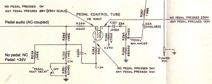
At first glance, the core of the solo oscillator may look like an astable multivibrator, with V1 and V2 oscillating at as a result of charging and discharging C13 and C14. However, on closer inspection, you can see that it behaves simply as two common-cathode amplifier stages cascaded, with the 2nd coupled back to the first (resulting in positive feedback), and the first stage having a tunable LC tank at its input. The tank forms a resonant filter, and thus the circuit oscillates at its resonant frequency. C13 and R4 are not used for timing the oscillation, but simply for coupling and biasing, and have clearly been chosen to have a time constant much longer than the longest oscillation period. The tank circuit consists of up to 18 capacitors and 37 inductors. Twelve of the capacitors are optionally shunted into circuit by the "big steps" and "small steps" tuning switches, lowering the resonant frequency. Three are optional "tuning trimmer" capacitors, which may or may not be added by the factory. The inductors are used to tune the oscillator to the key being played; the lowest key makes use of every inductor, while the highest shorts out all but one. The output of the solo oscillator is almost a square-wave (due to V2 being overdriven), which is then high-passed and rectified by V3 to form a narrow pulsed waveform. It is then rectified again to change the polarity of the pulse, which is then used to trigger a bistable multivibrator, resulting in frequency division. My first impression of the rectifier/driver stages was that they aren't necessary, since bistable dividers can be designed without, and usually are. However, note that the "strings-family" sounds are taken from these stages; such waveforms would be unavailable without these otherwise unnecessary circuits! As for the "woodwinds-family" sounds, the Bass and Tenor registers use square-waves taken from the plates of the frequency dividers. Yet, the Soprano register, rather than taking the square-wave signal from the plate of V2, takes the sine-wave signal at the cathode of V1! Before realizing this, I wondered if my instruments were faulty, since the Soprano woodwind timbre was so much mellower than the other two woodwind registers. Perhaps the Soprano voice is meant to imitate a flute, while the others most closely imitate clarinets. Now that we've looked at all of the oscillators, let's look at the pedal control tube circuit; in modern synth terms, this would be called the pedal envelope generator and voltage-controlled amplifier. This is, in my opinion, the most elegant and clever circuit in the whole organ:
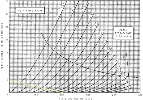
Yes, that's it—a dozen components and half a tube! So, what's going on here? How can one triode of a 12AU7 possibly be used as a VCA when the solid-state guys are using operational transconductance amplifiers consisting of dozens of integrated transistors, not to mention the external parts? We'll get to that. First, let's talk about the envelope section. This consists of components R259, R260, R261, and C220, as well as the "Pedal Fast Decay" tablet. The envelope is basically an attack-release (AR) type, with attack time constant of about 10 ms, and two settings of release time. When a pedal is pressed, C220 charges through R259 to nearly 34 volts (forming the attack), and stays there for the duration of the pedal-press. When the pedal is released, C220 discharges, either through 1MΩ or 9.2MΩ, thus forming the release with a time constant of 100 or 920 ms. This envelope voltage is combined with the pedal audio signal via R262, then applied to the grid of V8 through grid-stopper resistor R254. As for the VCA section, it works by taking advantage of the non-linear plate characteristics of the 12AU7. As shown by the curves below, the 12AU7's gain decreases as the grid voltage decreases, until eventually it is completely cut-off. For example, using the load-line drawn (for 47kΩ plate resistance and 206V plate supply), the voltage gain for -2V of grid bias is about 16, at -6V about 11, at -10V about 9, at -14V about 6, and after that, well, it approaches zero quite fast.
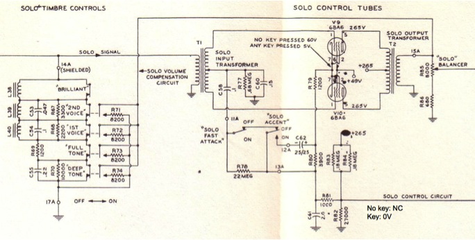
Of course, there are some problems with this VCA design, one being the sharply decreasing gain as the grid/control voltage dips below about -14V. The distortion also undoubtedly increases simultaneously. However, this is of no practical concern in this application, since distortion of bass frequencies is less objectionable than at higher frequencies (and to be honest, it is hardly noticeable). Another problem is the shared issue of all single-ended VCAs that I know of: control-voltage feed-through, where the output voltage swings with the envelope. Again, in this application, this is not a problem, since it gives a bit of a "thump" to the attack (good for accentuating the bass note), and is not audible in the release due to the sub-sonic time constants. As well, the coupling capacitor C221 is small, forming a high-pass filter with the loading resistors. Considering just R255 and R256, the cutoff frequency is 68 Hz, which would certainly cut down on thumping, at the expense of some low-end response (again not practically noticeable—perhaps compensated for in the subsequent amplifier stages?) Note that on the model S, half of a 6SN7 is used instead of a 12AU7. The 6SN7 is somewhat higher-gain and more linear; it has less variation of gain with bias point, making it a poorer choice than the 12AU7 for this circuit, though undoubtedly still fine. The S and S-1 have a functionally identical but slightly different circuit to the S-4, where instead of the cathode being positive and the grid normally grounded, the cathode is grounded (through 680Ω) and the grid is normally negative. It was undoubtedly changed as a result of eliminating the field coil speaker, since without the field coil (or some big warm power resistors in its place), there isn't a high enough negative voltage produced in the power supply; even with various additional resistors, the S-4 only has a -23V maximum, whereas the S and S-1 have -37V and -35V respectively. (Yet, the S-6 has -30V, but is based on the S-4.) Next, let's look at the solo control circuits of the S-4, which consist of an envelope generator, a VCA, and filtering & volume-compensation circuits:
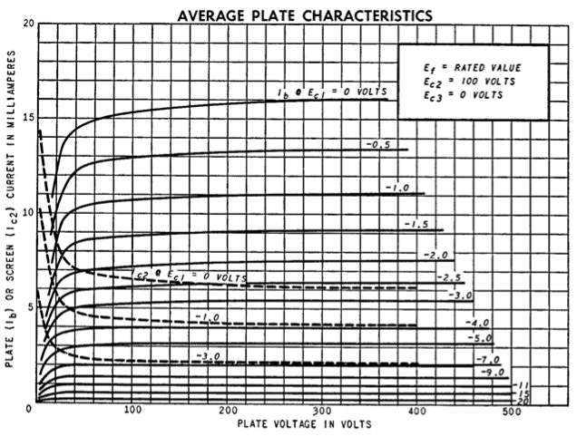
On the left are the passive filtering elements that affect the solo signal prior to the VCA; the manual describes this section well, so I won't discuss it besides pointing out that it exemplifies the "formant"-type filtering technique common in electronic organs, but completely ignored by Moog and his contemporaries in favor of sweepable filters with otherwise simpler response characteristics. More on that later; for now, we will look at the solo control circuit. Like the pedal control circuit, there is basically an envelope generator and a VCA, though the two are quite intermingled this time. The envelope can be considered either an attack-release (AR) or attack-decay-sustain-release (ADSR) depending on the tablet settings. The VCA uses a differential signal (i.e. it is balanced), pentodes as the variable-gain elements, and the gain is controlled at both the cathodes and the grids. 6BA6 pentodes are used, which are known as "remote-cutoff" / "variable-mu" types, meaning that it takes a very large negative voltage to bias the tube into cutoff as compared to normal pentodes. You can see that as the tube is biased towards cutoff, gain decreases even more nicely than the 12AU7 in the pedal control circuit.
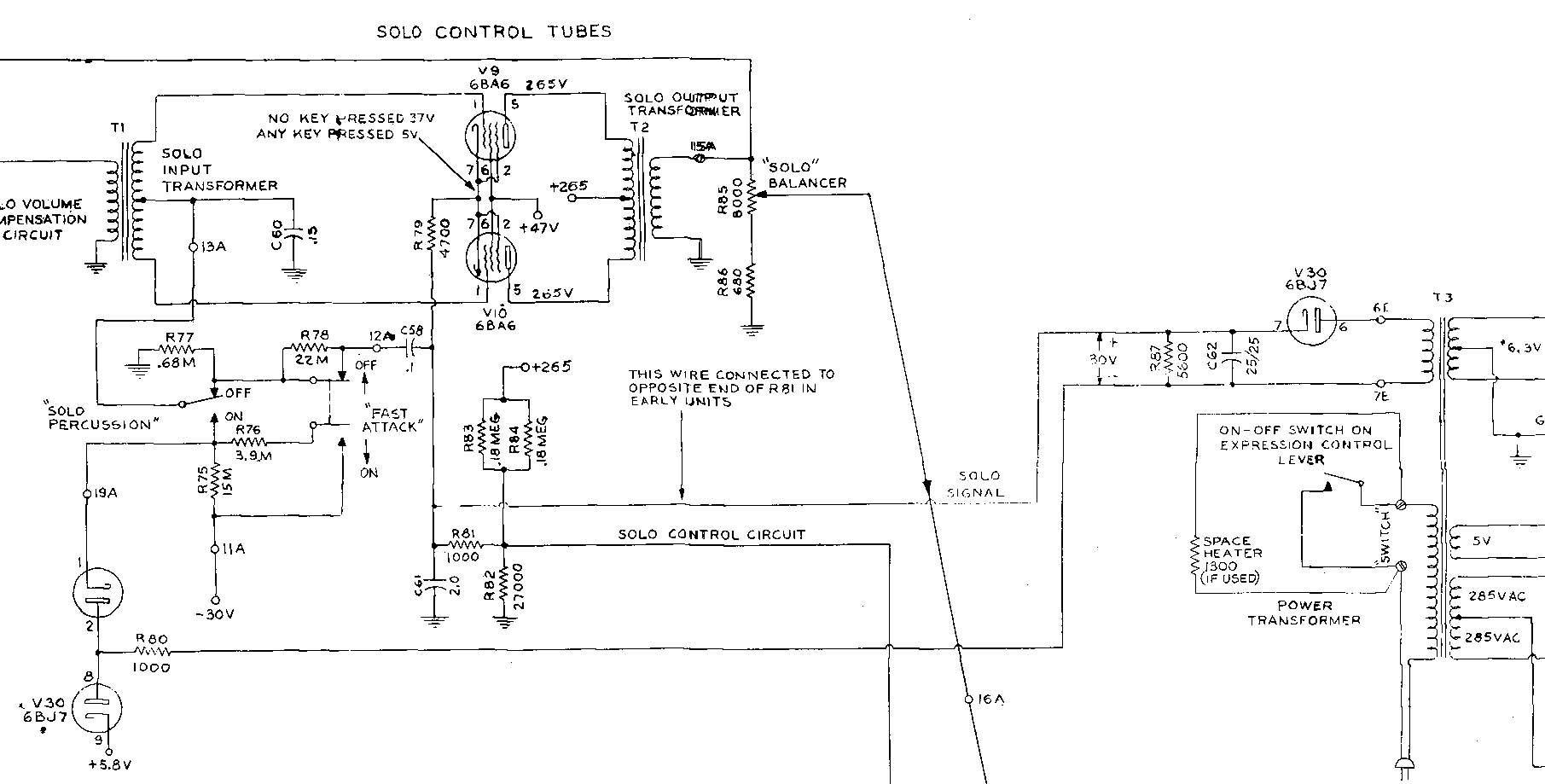
When both the "Solo Fast Attack" and "Solo Accent" tablets are off, the envelope is an AR type with relatively slow attack and instantaneous release. When a key is pressed, the node labeled "solo control circuit" goes from about 65V to 0V, quickly discharging C61 and pulling the cathodes of V9 and V10 low. However, the grids are also pulled simultaneously low by the capacitive divider of C58 and C60, preserving the cut-off bias condition for an instant. Then, the capacitors discharge through R77, forming the gradual attack; when fully discharged, the grid bias is zero, and thus the grid-to-cathode voltage is at its minimum, so the pentodes are fully amplifying. On key release, C61 is charged through the voltage divider, bringing the cathodes back to 60V, and the grids also momentarily high. Yet, because the grids only go up to roughly 20V while the cathodes go up to 60V, the tube is completely cut-off throughout this "release" portion of the envelope. Note that although it would be nice to have a gradual release, it is impossible with the given solo oscillator design, since the tuning contacts do not latch upon key release. When the "Solo Fast Attack" tablet is on, C58 is effectively disconnected; R78 is 22MΩ, which is too high to cause noteworthy current in C58, so the attack is practically instantaneous. When the "Solo Accent" tablet is on, it not only disconnects C58, but also connects large capacitor C62 across R80. Since C62 is entirely discharged (by R80) at idle, it effectively "shorts out" R80 momentarily upon key-press, bringing the cathode voltage lower than usual for an instant. The lower the cathode voltage, the higher the bias current, thus the higher the VCA's gain. Then C62 gradually charges up to the normal voltage across R80; this forms the "decay" of the envelope! By using a balanced design, the problem of control signal feed-through is eliminated. This is because although the bias of V9 and V10 changes with the control voltage, both tubes change simultaneously. Since the output transformer gives the difference of the current signals, the shifting bias is cancelled out. Note that the behavior of this circuit is the major difference between the S-4 and S-6. On the S-6, while the "Solo Fast Attack" tablet has the same function, the "Solo Accent" tablet is changed to "Solo Percussion". It can be understood as converting the ADSR envelope with high sustain level to an ADSR envelope with zero sustain level—it becomes an attack-decay envelope with instantaneous attack, and two decay settings. Here is the schematic for the S-6's solo control circuit:
It is similar to the S-4, but with an extra tube: V30, which is a 6BJ7 triple diode. One diode is used as a power rectifier along with C62, R87, and an extra transformer winding to set up a floating 30V DC supply. The other two are used to discharge the envelope capacitor upon key release, and give proper grid bias when no key is pressed. As with the S-4, I will explain the circuit's operation step-by-step. When the "Solo Percussion" tablet is off, the circuit is nearly the same as the S-4. On key-press, the cathodes are pulled low, and the grids are pulled low momentarily by C58 and C60, as long as "Fast Attack" is off. C58 and C60 are then discharged by R77, forming the gradual attack. When "Solo Percussion" is on, the grids are no longer pulled towards ground by R77. Rather, they are pulled towards what I'll call "almost-ground" by the first diode of V30. As in the S-4, when no key is pressed, the "solo control circuit" line is pulled tens of volts positive by the voltage divider. But in this case, some voltage is dropped across R81, then 30V is dropped across R87/C62, then more across R80. The third diode of V30 limits the voltage at the left side of R80 to slightly over +5.8V, and the first diode then drops some of this voltage as current flows in R75 (and R76 in parallel, if "Fast Attack" is on), thereby giving close-enough-to-zero volts at the grids such that the pentodes remain cut off. Then, when a key is pressed, the "solo control circuit" line is grounded, bringing the cathodes and the positive side of the floating +30V supply down to roughly 0V. Therefore, the negative side of the floating supply is about -30V relative to ground, reverse-biasing and hence turning off both diodes connected to R80. C60 then charges to -30V gradually through high-value resistor R75 (and optionally R76), forming the decay portion of the envelope. When the key is released, C60 is very quickly discharged by V30's first diode. This concludes my explanation of the S-6's circuitry. In all, I can say that like the vast majority of tube-based designs, the circuits are remarkably elegant and easily understood. After all, the incentive (to give reasonable cost) was to use the fewest components possible, especially tubes, so a great deal of thought was put into how to make simple yet functional circuits. Today, while digital designs may use few physical components, usually they are centered around one or more integrated circuits that contain thousands if not millions of integrated parts, and which may also contain proprietary firmware—absolutely inelegant and incomprehensible in comparison. By virtue of their simple discrete designs, Hammond's chord organs are very easy to repair, and will remain serviceable indefinitely. I should mention again the remarkably well-crafted and comprehensive service manual covering models S, S-1, and S-4, which can be found here, and the excerpted schematics and wiring diagrams of the S-6, which can be found here. As well, it is worth noting that there is a section about the chord organ in the 1st and 2nd editions of Electronic Musical Instruments by Richard H. Dorf (the 2nd edition of which I have already mentioned twice). There are three editions, with the 1st (1954) and 2nd (1958) being mostly the same and all about vacuum-tube instruments, while the 3rd (1968) is completely redone and mostly transistorized. All editions are extremely well-written and informative, probably the best texts on electronic organs (and "pre-Moog" synthesis generally) ever created. They discuss both the designs of specific products, as well as principles for design. By the way, those product from Allen, Conn, Hammond, Lowrey, Minshall, etc. usually have full schematics given. As well, the 1st edition describes two unique instruments for the reader to build using off-the-shelf components: the monophonic "Thyratone" (named for its use of thyratron tubes), and polyphonic "Electronorgan". The 2nd edition also describes the "Thyratone", but replaces the "Electronorgan" with a section about Schober organ kits. Addendum 12/24/2022 A reader who goes by "human-potato_hybrid" has scanned for me a document explaining how to install Hammond's kit for adding spring reverb to the S through S-6 chord organs. It involves adding a "necklace" style reverb unit, an additional amplifier chassis, and an extra speaker either on top of the organ or on the floor beside it. Voice-coil signal from the organ is applied to the reverb send coil via a passive network of resistors and incandescent bulbs. Signal from the other end of the spring is amplified and fed to the additional speaker. Separate dry and reverb speakers may seem strange, yet it is undoubtedly a richer-sounding system than the usual combined one. The SoundsBy now, if you haven't heard already, you probably want to hear what the thing sounds like! I've compiled some of the best video demonstrations I could find on YouTube, which are shown below. The first two are 1950s promotional recordings by Hal Shutz. The organ used for the left demo is undoubtedly an S-6, since it exhibits the "Solo Percussion" feature introduced in that model: Next is a 1950s short promotional film, which shows a wide variety of sounds and styles while the organ spins slowly on a rotating table. Note the charmingly direct and cheerful '50s marketing style. Too bad there is some pitch jitter, which is a fault of the video, either from poor film transferring or digital encoding. Note also that the back of the organ has a cover, probably installed specifically for the film. This organ is also an S-6, again as indicated by the presence of "Solo Percussion". Next are some relatively recent videos; the one on the left shows some nice arrangments of Christmas carols on an S-6. The one on the right is a basic demo of a Model S; you can hear that the sound is virtually indistinguishable from the S-6. Lastly, here are some videos of a Venezuelan style of music called Zuliana Guaracha. A reader informed me that the S-6 is a standard feature in these groups from the '70s to the present day, and there are apparently more than 30 groups active as of early 2021. Some groups include Los Brillantes, Alfredo Rojas Y Su Caribe Show, El Gran Caribe de Numan Medina, Los Masters, Microcombo Dabajuro, and Los Reyes de Juan Torres. The chord division is always ignored, but the organ and solo divisions are used for playing intricate melodies, often augmented by heavy reverb. More good examples can be heard here, here, here, here, here, here, and here. Thanks Ronny! At some point, I hope to record a short video of my playing, since I've developed a style quite different from what is normally heard on these organs. Until then, enjoy the YouTube videos, or your own playing—I imagine many readers of this article probably have their own chord organs! As well, if you find even better demos, I could embed them here. Most Important Links
|
| If you notice any errors or have additional information that you would like to add, please contact me! |


First Published: 11/27/2019