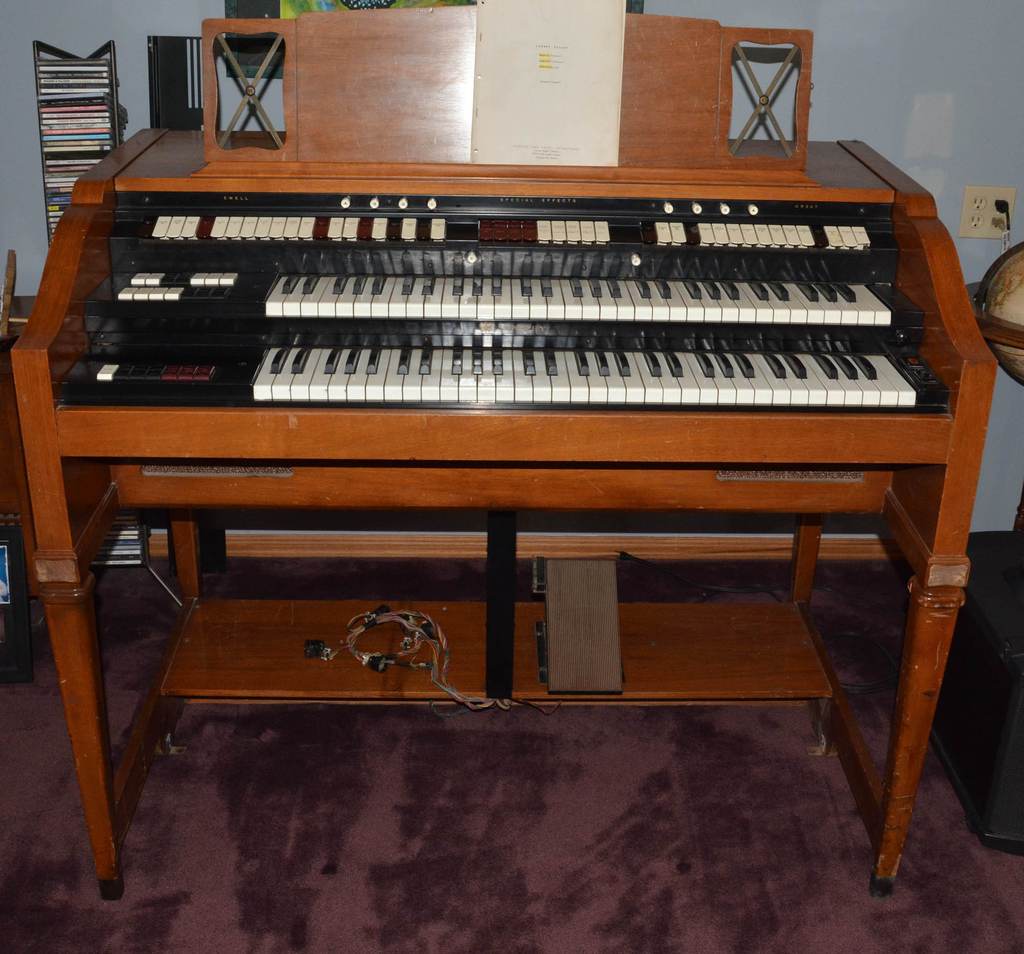
Lowrey "Festival" model FLElectronic Organ
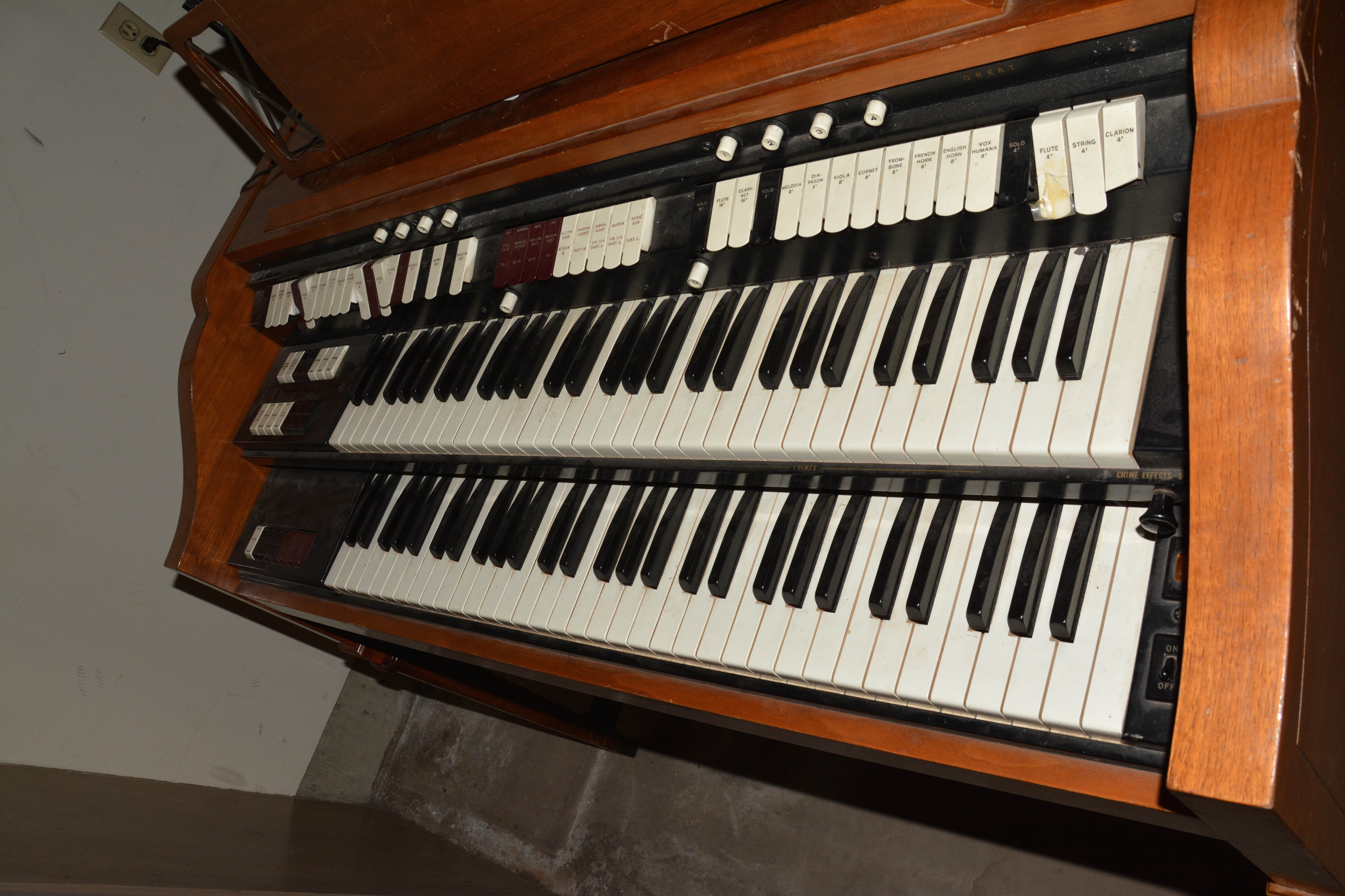
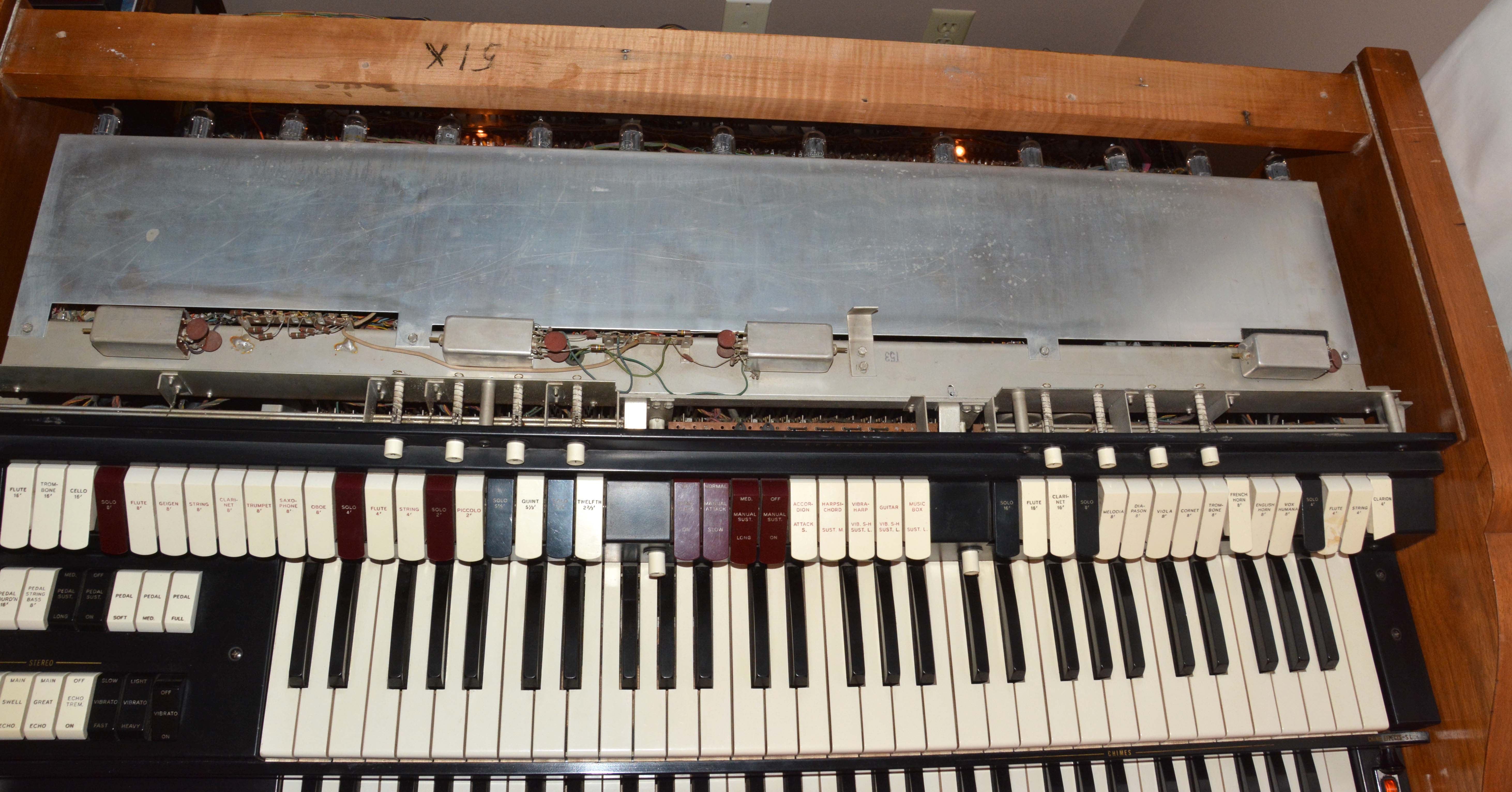
This article describes the Lowrey "Festival" model FL, as one of a series of articles on my favorite class of instruments: vacuum-tube organs. Why are tube organs my favorite, you may ask? Because they are universally well-built, attractively styled, fun and easy to work on, and unique and satisfying in tonal quality. Simply put: they look cool, they sound great, and they can last forever. They even smell good, and their warmth makes me warm on the inside (to paraphrase my German friend Bernd)! Lowrey's "Festival" FL model was introduced in 1959, along with the electronically identical models CH and CN: "Church" and "Coronation" respectively. These were the first full-sized Lowrey organs (not counting one unsuccessful early model of the late 1940s, no examples of which survive, to my knowledge), each having two 61-key manuals and a 25-note pedalboard. The FL exhibits a "four-poster" cabinet design (with open space in the knee area), in imitation of certain Hammond organs such as the famed B3, while the CH and CN are designed like normal pipe organ consoles, the Church model being more traditional and heavily built than the Coronation. Unlike Hammond's four-poster models, the FL contains internal speakers and amplification: a 12" woofer and a rectangular horn tweeter, driven by a built-in power amplifier of 40 watts. The CH and CN models have a 15" woofer, made possible by the extra space available in the enclosed lower portion. All models produce a good variety of satisfying tone colors, and have useful variations in expression (sustain, slow attack, staccato, etc.), which are the basis for real musical enjoyment and achievement. Especially when installed domestically in acoustically "dead" rooms, they do not sound very much like pipe organs, but I have no problem with this, since I don't find the comparison with a pipe organ all that useful or necessary. In fact, a large part of why these organs are so interesting and worth saving is because they have distinct sounds of their own that also happen to be satisfying and beautiful. Except for its use of silicon diodes in the power supply and vibrato circuits, the FL is a vacuum-tube instrument. In total, it uses 89 tubes, the highest count of any tube Lowreys. Power consumption of the tube heaters alone is about 246 watts! As well, roughly 260 neon lamps are used, mostly for keying the sustain registers of the swell manual, and for facilitating the swell-to-great manual coupler. The underlying design is much like other tube Lowreys, with a frequency-divider tone generation system producing squarewaves, a combination of direct and electronic keying (the latter for the upper-manual 8'-4'-2' registers), and tone shaping via tuned filter-amplifiers. It has a STACCATO tab, indicating that sustain behaves in a "reverb-like" way instead of "true sustain" like some other Lowrey models (see the LS article and the circuit description further down for more info). Since my Lowrey "Holiday" model LS article goes into reasonable depth about the history of Lowrey's tube organs, and explains many of the same circuits and design principles used by the FL, this article will mostly address the repairs I performed on my instrument, and some of the really noteworthy aspects of the design as compared to the LS. At the bottom of the page, there is a video demo. My FL is working well, after the various repairs explained below. For about a year since I acquired it, it was missing its pedalboard, but I have since acquired an SS-25 pedalboard and modified it to work properly. Also, as a courtesy, I have scanned and uploaded the schematics of the FL/CN/CH to this site, which you may download free of charge here. I've also uploaded the owner's manual, which I found already scanned on an obscure archived site. Features
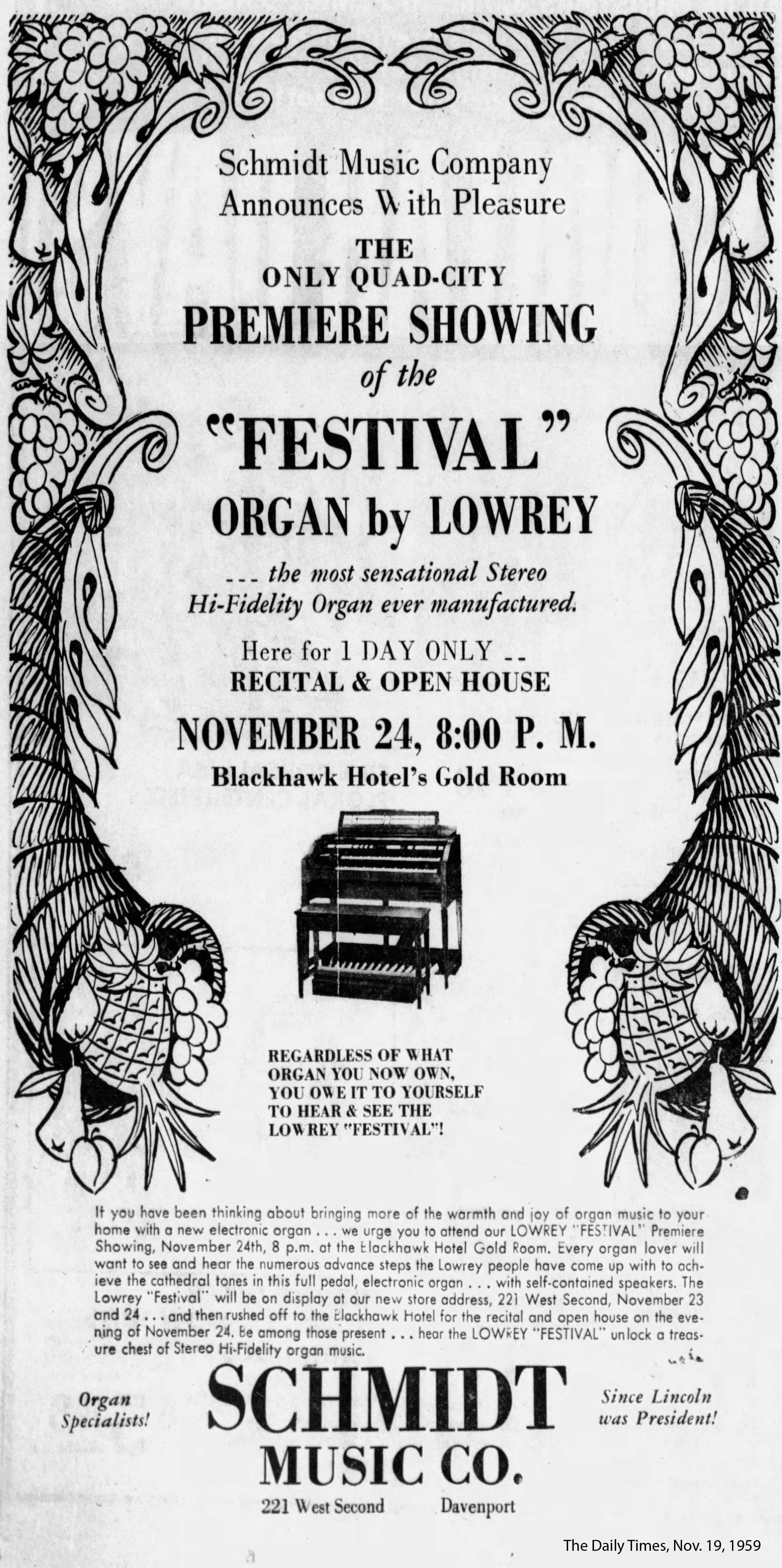
HistoryI have already covered the overall history of Lowrey and their tube organs in my Lowrey LS article, so this section will be quite short. As stated there, Lowrey's "Festival" FL model was introduced in 1959, along with the electronically identical models CH and CN ("Church" and "Coronation" respectively). These were the first full-sized Lowrey organs following the "Berkshire" model S (their first successful self-contained model), each having two 61-key manuals and a 25-note pedalboard. Lowrey made only a handful of other full-sized tube organs: the unsuccessful "Lowrey Electronic Organ" introduced 1947, the "Lincolnwood" SS-25 introduced in 1961, and the "Deluxe" models SSO-25, FLO, and CHO from 1963. The latter three models are basically the same as one another except in cabinetry and lack of a built-in Leslie on the FLO; they are also much closer electronically and functionally to the SS-25 than the FL/CN/CH. Like all tube Lowreys, they were manufactured by Hallicrafters in Chicago, Illinois. Incidentally, the Hammond organ company was also located in Chicago, and manufactured all of their best organs there. Some interesting context can be added by looking at advertisements for the FL; below are four typical ones, the first three from newspapers (via newspapers.com), and the fourth from a magazine (from some ad seller on eBay):
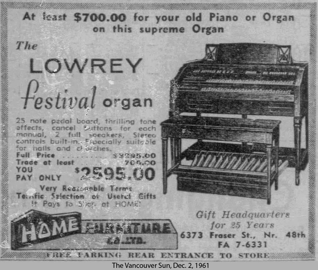
Despite being a full-sized instrument, the Festival was marketed towards householders primarily. It was also marketed as being especially easy to play, despite having none of the numerous playing aids that would appear in later (chiefly solid-state) organs, such as drum machines, automatic bass, arpeggiation, repeat percussion, one-finger chords, and so on. Physically speaking, it is no easier to play a given tune on the FL than it is on the average tube (or, in fact, pipe) organ, though the resulting musical impression may be more or less pleasing for various reasons. I, for one, am glad the FL contains no such "features", since design emphasis is instead placed on providing a good variety of satisfying tone colors, as well as useful variations in expression (sustain, slow attack, staccato, etc.), which are the basis for real musical enjoyment and achievement. Especially by the 1970s, too many organs were made with huge drum sections, auto-bass, auto-chords, reverb, built-in Leslies, and so on, yet a small selection of mediocre—often entirely mushy—stops. Classic 1950s buzzwords "hi-fidelity" and "stereo" also feature prominently, despite that the FL cannot strictly be considered either. "Hi-fidelity" refers to a high quality of reproduced sound, yet since the instrument creates its sounds from scratch, no reproduction occurs overall. You could argue that the amplifier and speakers are hi-fi when considered alone, which is true; however, it is trivial, since practically all organ amps and speakers are hi-fi by '50s standards, even from the early days of the '30s and '40s. In fact, the largest limiting factor in the fidelity of early sound equipment was usually the source itself, such as the 78rpm phonograph, tape or wire recorder, or low-bandwidth AM broadcast signal. It was only around the late 1950s that really "hi-fi" sources became common, which were then able to fully exploit the existing amplification and transduction technology. As for "stereo", while there are indeed two audio output channels (called "main" and "echo"), the signal routing options are extremely limited, there are no stereophonic effects to add breadth (except those achieved acoustically), and in fact, the speakers fed by the two channels are usually dissimilar and asymmetrically located, thus following a different concept than a normal stereo hi-fi system. To be more specific, each manual's signal can be routed either to one channel, the other, or both equally, while the pedal signal is always routed to both equally. The "echo" channel usually goes to a Leslie cabinet placed to one side of the organ, while the main channel sounds through the built-in speakers. The point then is mainly to have a selectable Leslie effect. Don't get me wrong; I love the Festival and think it really is a beautiful, satisfying, well-designed, and well-made instrument. But even in the 1950s, advertisers stretched the truth and made rather desperate associations with current trends. The difference is that back then, the propaganda was more direct and cheerful, whereas today it is insidious and plays more on anxiety than pleasure. Good luck finding a modern ad that is half as informative as the ones above, despite their exaggeration! You may also wonder how much instruments like the FL cost when they were new. Again, some old newspaper ads have the answer:
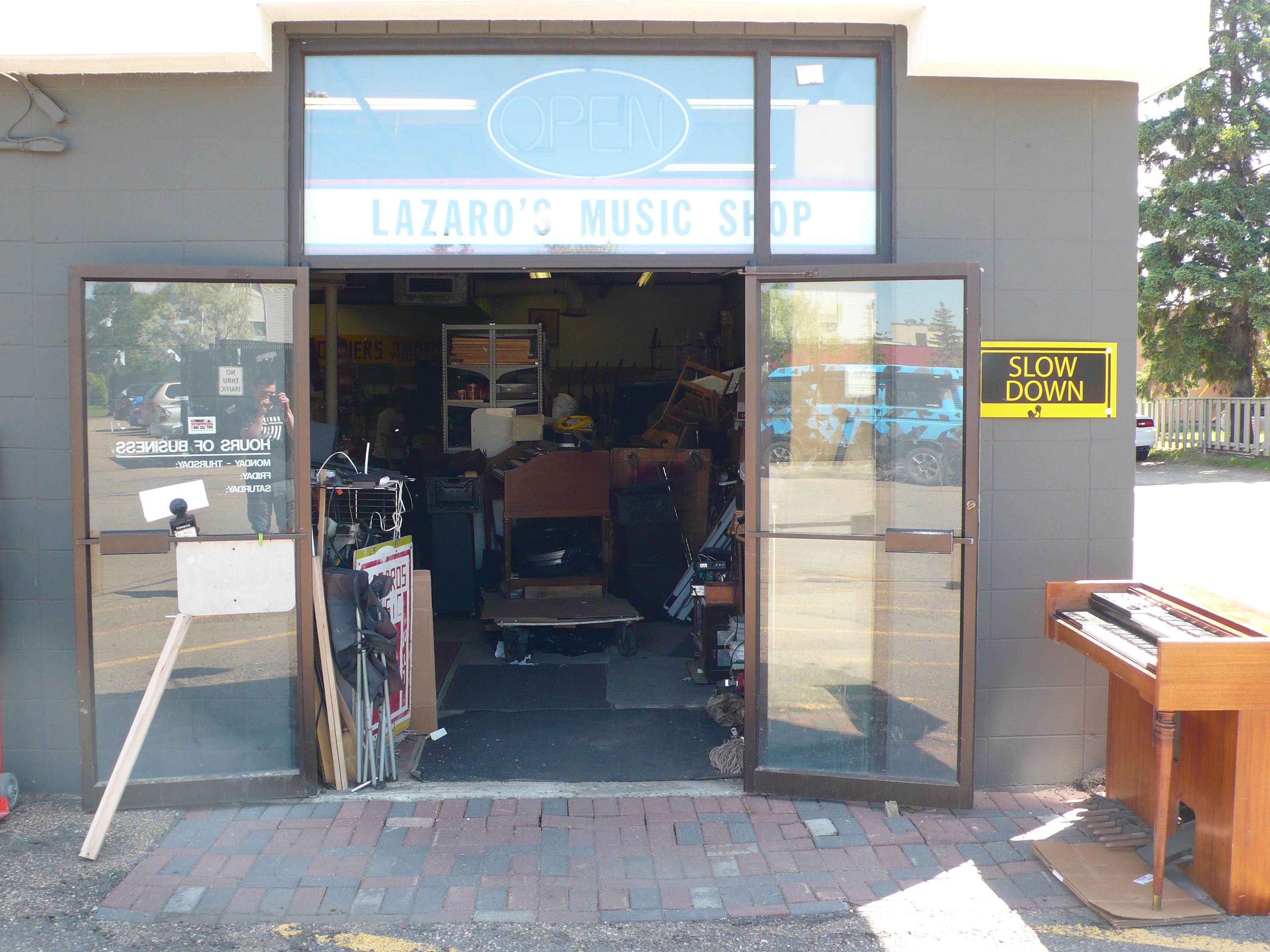
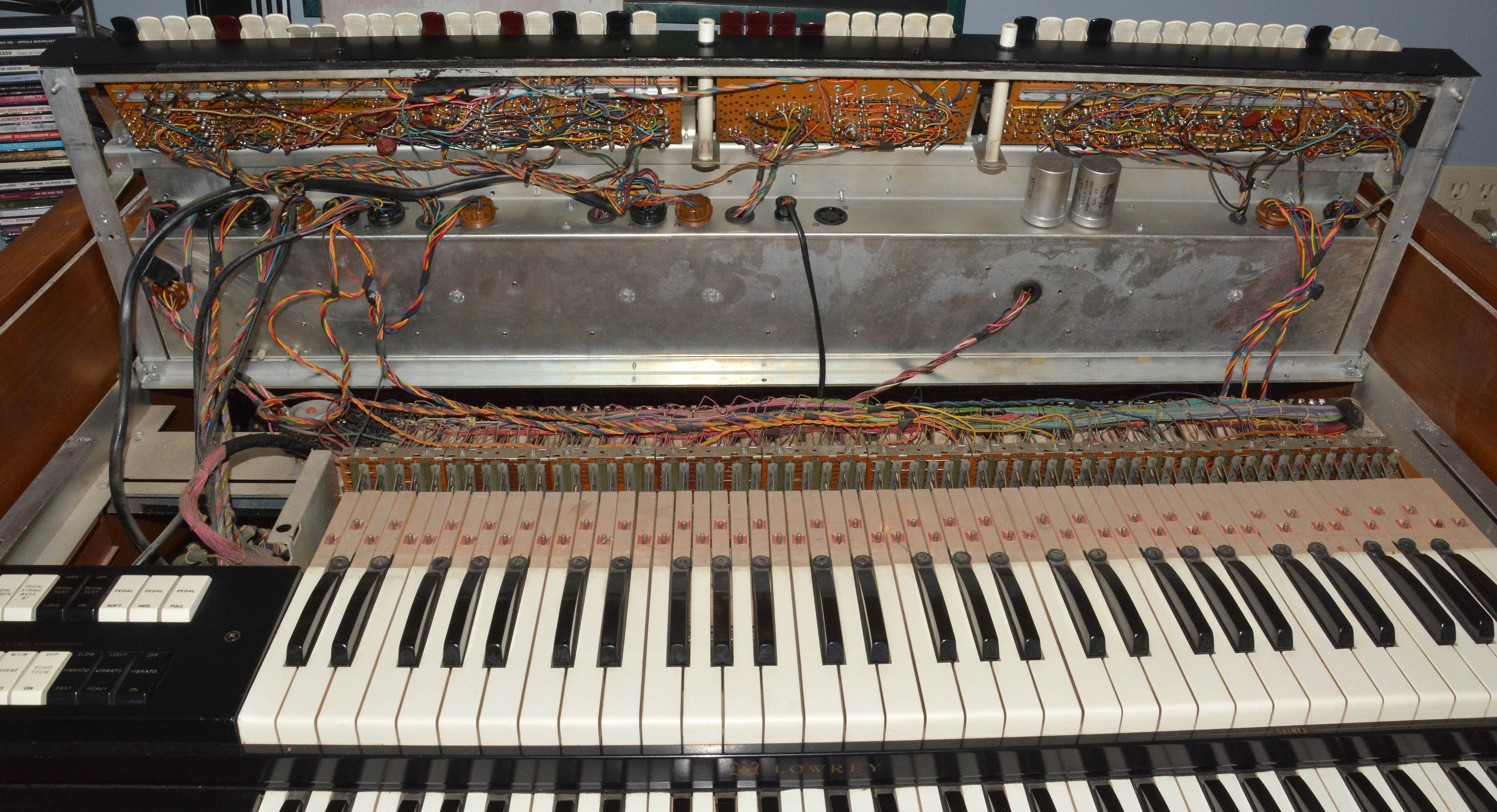
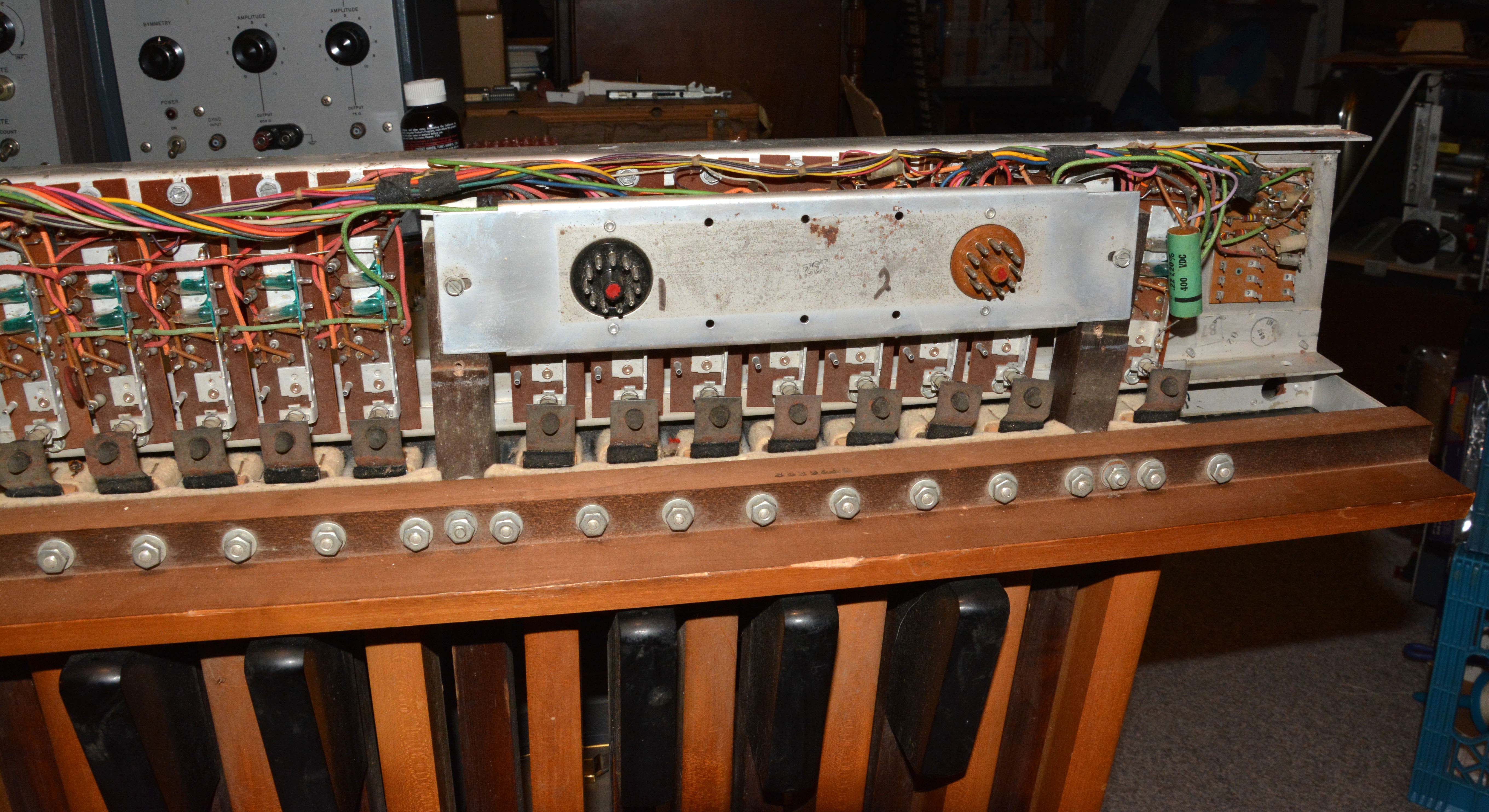
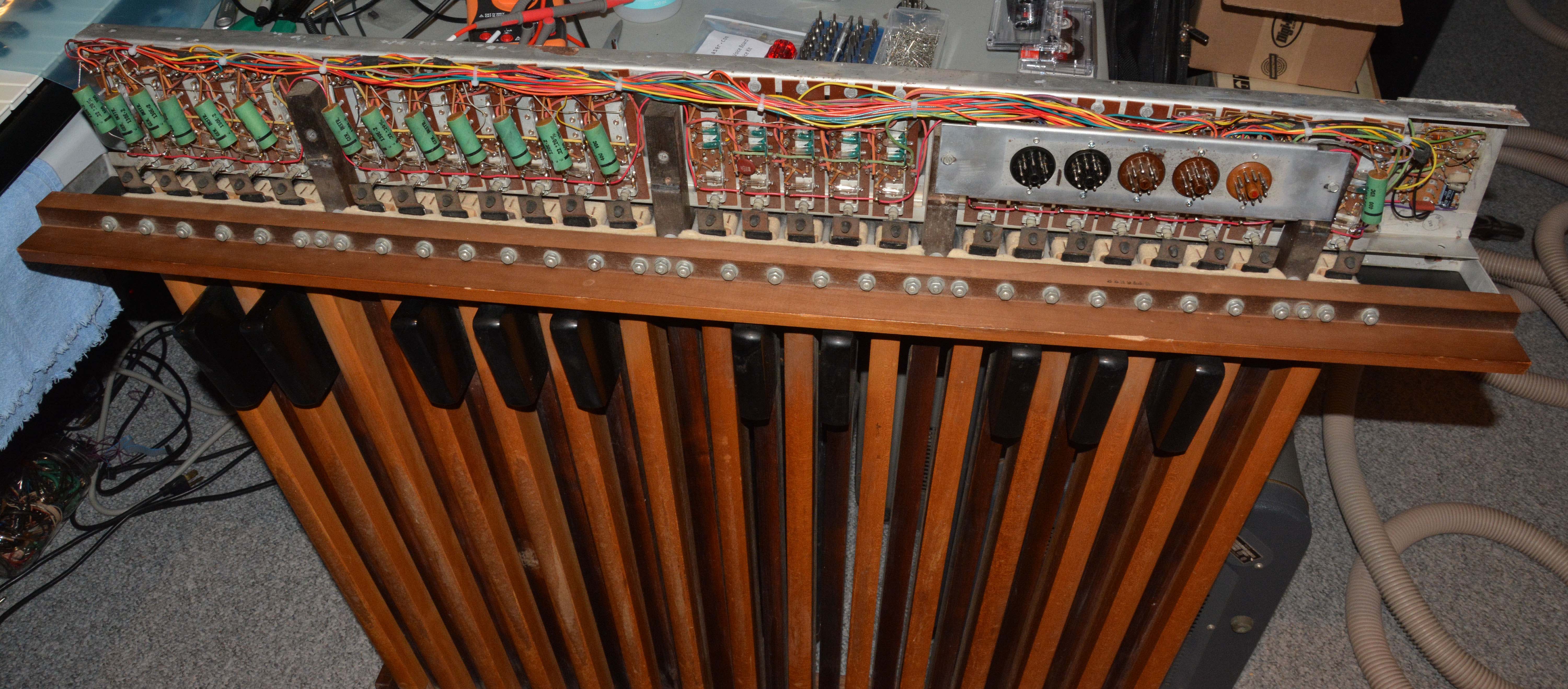
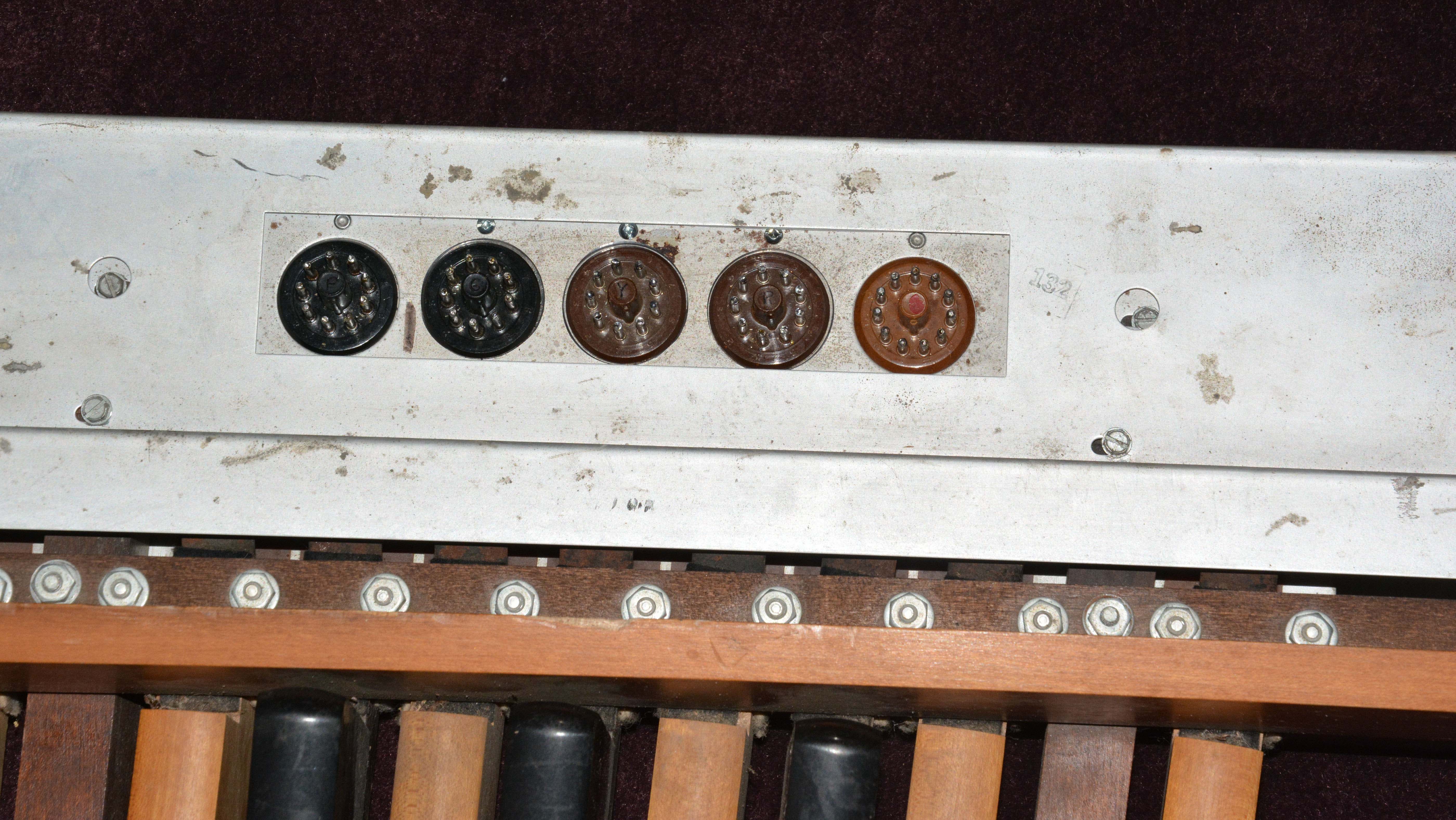
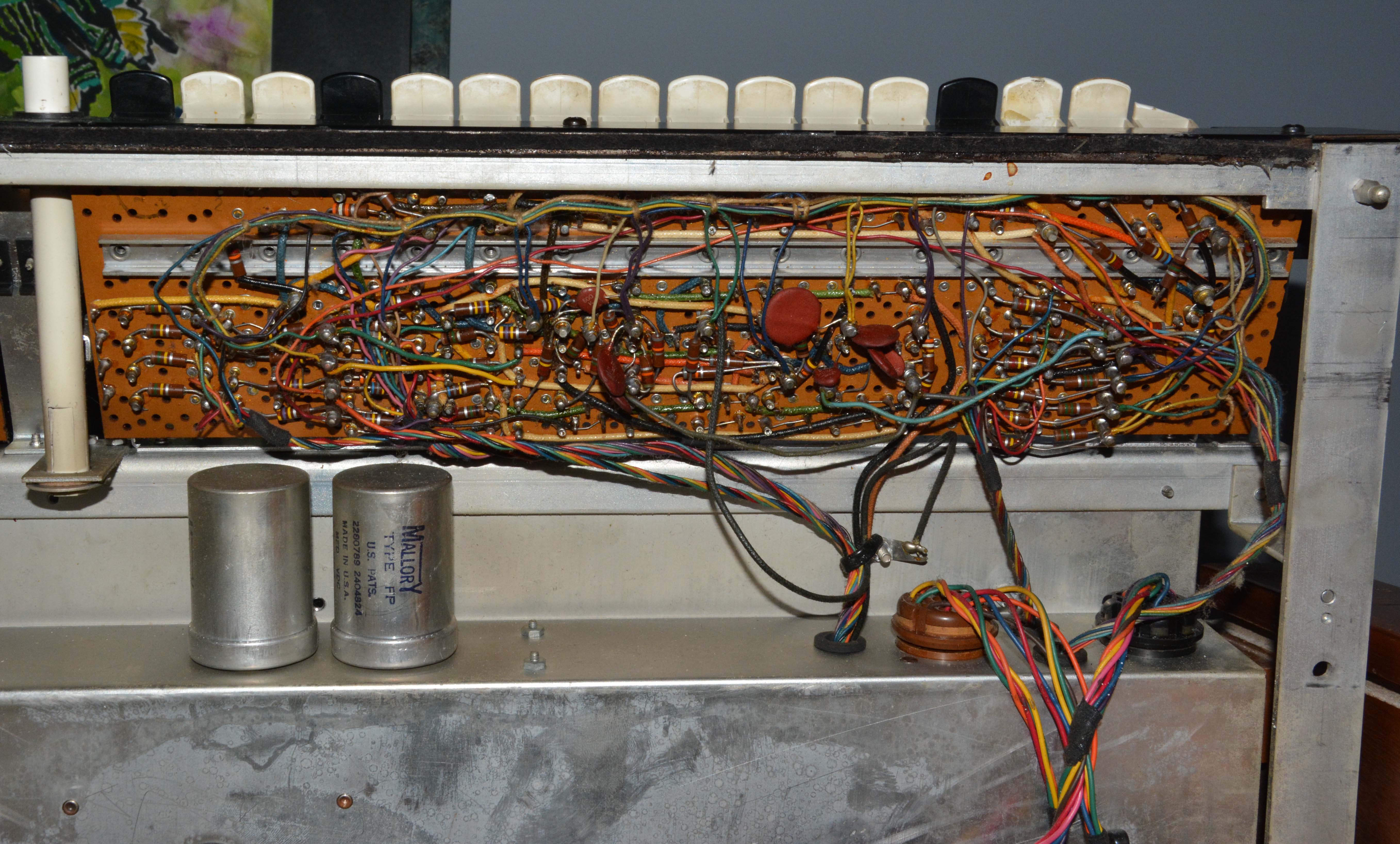
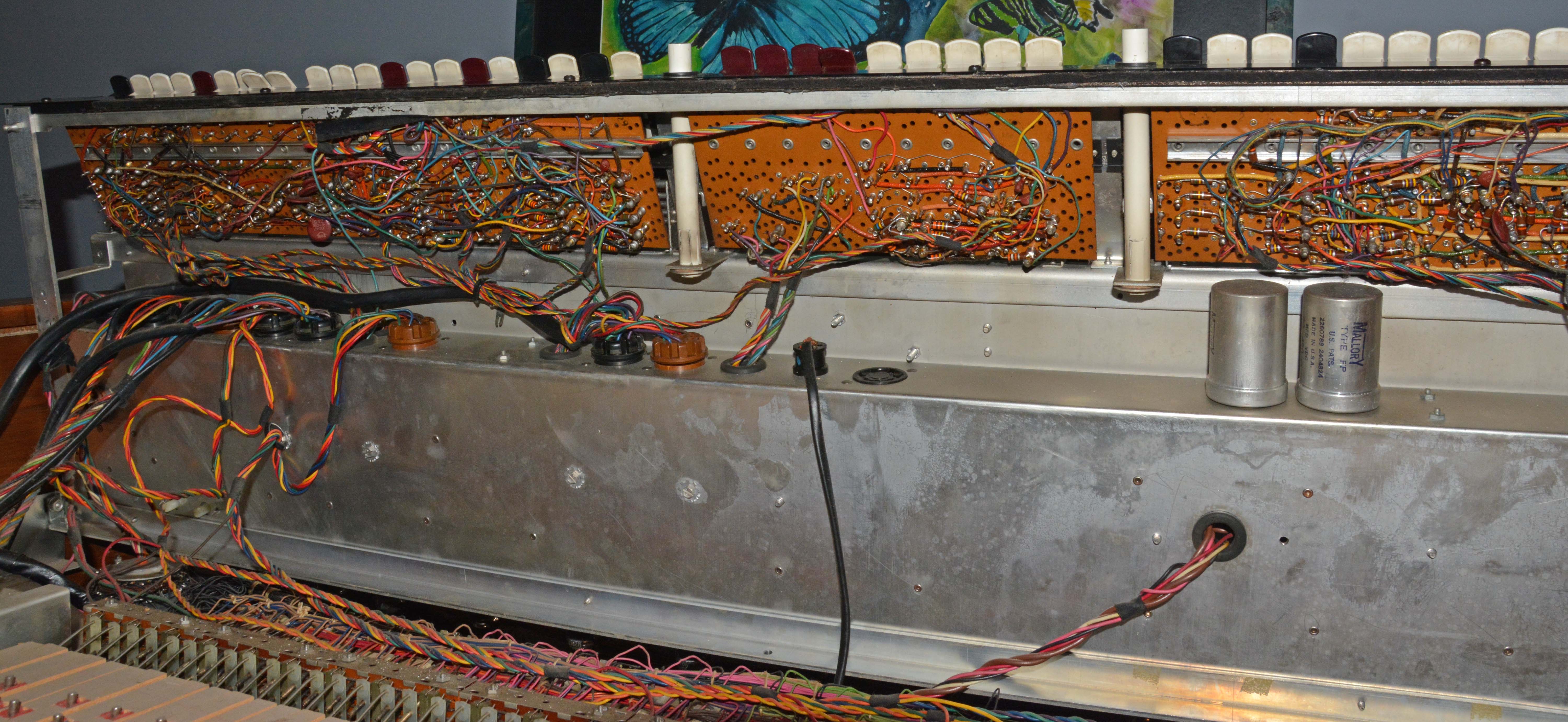
The left ad indicates a price of $3,295 CAD in late 1961, and the right shows $2,845 USD (as the "was" price, and note the different currency) in early 1964. From an online inflation calculator, these equate to $28,627 CAD and $24,153 USD respectively in 2020 currency. These prices leave no wonder as to why the instrument's build quality is far beyond any modern electronic keyboards, with finely crafted real-wood cabinetry, metal framework and chassis, hand-assembled circuitry, and really high serviceability! Another point to make is that, to my knowledge, the first organ with a "four-poster" cabinet design was the Hammond model A in 1935 (their very first organ), and by the late 1950s, the style was associated with their popular B3 model first offered in 1954. So, from the cabinet alone, we can say that the FL was styled in imitation of a Hammond organ, likely the B3 in particular. While the two instruments have identical clavier spans, the timbres of the FL are controlled by stop tabs instead of harmonic drawbars, and its tone shaping system is essentially subtractive rather than additive, so it typically sounds different—brighter, fizzier, more resonant, and more overtly "electronic". In the FL's system, most stops involve squarewaves—octavely combined to introduce even harmonics—passing through resonant filter-amplifiers that imitate acoustic formants. For a particular stop, frequency emphasis remains constant no matter the note being played, and therefore the harmonic content of the resulting note changes considerably over the keyboard's range. Conversely, Hammond's tonewheel system generates sinewaves, which are then added in fixed proportions selected by the drawbars, giving the same harmonic content to all notes across the instrument's entire range, or at least until it runs out of tonewheels for the highest harmonics. In fact, the highest tonewheel generates about 5,920 cps (F#8), which is roughly 1.5 octaves below the upper limit of audibility. As well, Hammond's drawbars only go up to the 8th harmonic, and leave out the 7th since suitable pitches are not generated by the equally-tempered tonewheel system. Especially in the bass end where harmonics can be audible past the 64th, the insufficiency of this system is quite obvious. It is really impossible to generate any acoustic-type timbres on a Hammond, especially bright ones like strings or reeds, while they are readily available on a Lowrey. Of course, the tonal uniqueness and acoustic impossibility of Hammond's system makes it quite distinctive, and this combined with earliness and good promotion contributed to Hammond's immense success, and thus to the growth and success of many other electronic organ firms including Lowrey, who would eventually overtake Hammond's leading commercial position in the 1970s. I should mention that the FL can sound Hammond-like, especially on the upper manual, and this is by means of combining flute-family stops. These are filtered differently from the "orchestral" stops, such that they are fairly sinusoidal and consistently loud across their range, making them good for harmonic synthesis. If the 16' register is used as the fundamental, then the available harmonics are the 2nd, 3rd, 4th, 6th, and 8th (or, in footages, 8', 5 1/3', 4', 2 2/3', and 2'). This is not too bad, though we are missing the sub-3rd, sub-fundamental, and 5th harmonics present on Hammonds. As well, each register has only two loudness settings besides off, a less flexible situation than 9-step drawbars. Though turning on the STACCATO tab adds a slight "punch" to the attack, it isn't as pronounced as Hammond's key-click. There is no harmonic percussion, though a vaguely similar effect can be had by enabling one of the mutation stops (5 1/3' or 2 2/3'), avoiding the 16' register, and switching the ATTACK tab to SLOW; thus the fundamental tones fade in while the "harmonics" are constant, rather than the harmonics fading out while the fundamental is constant. The StoryThis organ has an especially funny acquisition story, which partly overlaps with that of the Lowrey "Holiday" LS. Like the LS, the instrument sat in the third and final location of Lazaro's Music in Edmonton for roughly four years, despite that it was in plain view near the front of the shop, and that Lazaro continually tried to give it away to customers. In late May of 2019, my good friend Noah and I tried powering it, and found that while the power lamp and tube heaters glowed, absolutely no sound was produced no matter the settings. Many keys were prone to sticking at the bottom of the lower manual, some of the rightmost tongue tabs were damaged, everything was rather dirty and beat-up, and the pedalboard was missing. Since at the same time we were checking out the model LS, which was missing all 36 of its 6X8 generator tubes, we decided to pull them from the FL. During the shutdown of Lazaro's in late June of 2019, I was given permission to remove the remaining tubes from the FL. I did not decide to bring the whole organ home at that point, considering all of its problems, besides its immensity; I was also turned off by the immense number of Couplates and "packs" used. Below are photos of the instrument as it was at the beginning of the end of Lazaro's; in the second image, the one-legged Holiday LS can be seen waiting for pickup, while the FL remains inside.
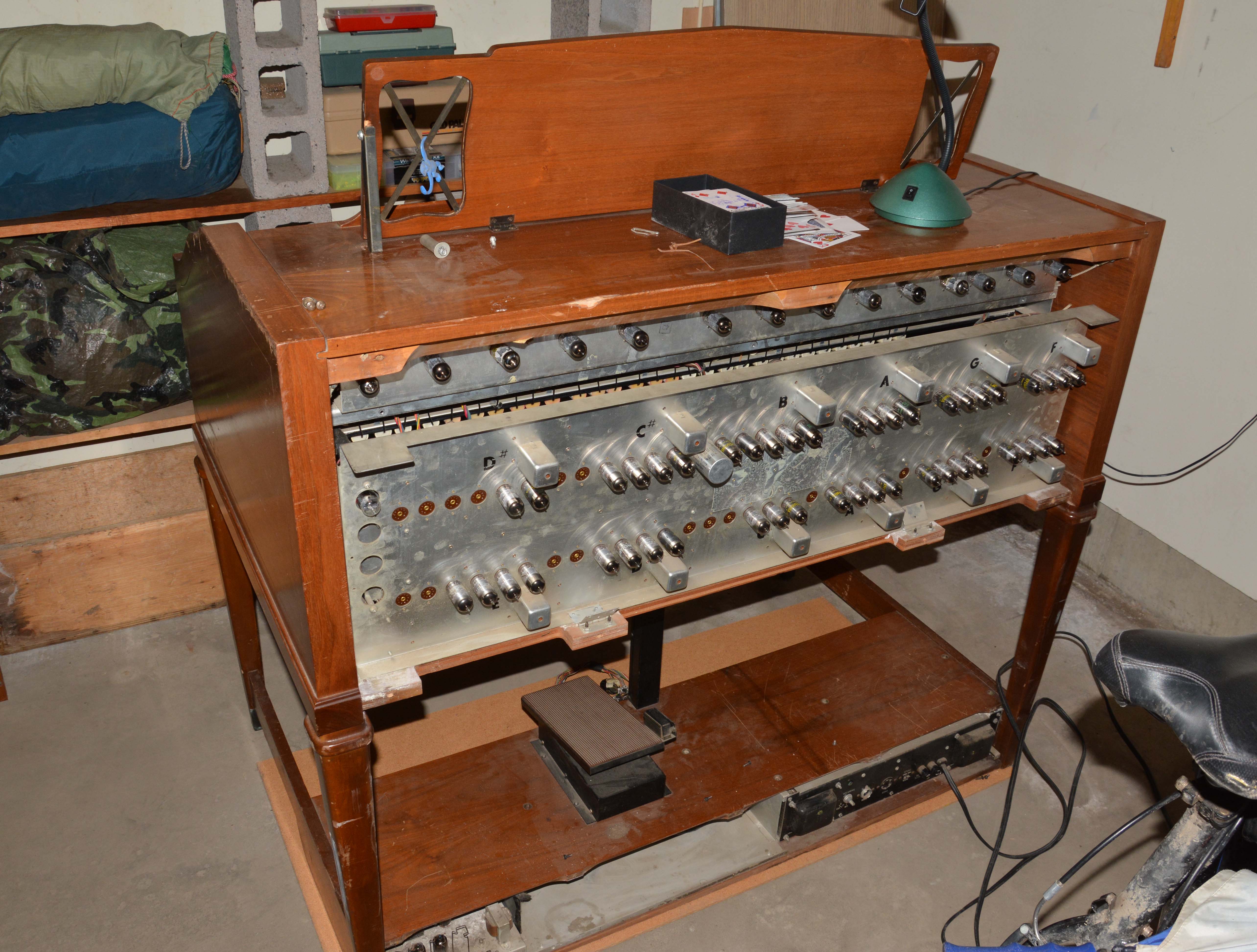
Over the next few months, I occasionally wondered what became of the poor thing. Then, in late October of 2019, a Kijiji ad showed up entitled "Vintage Lowrey Organ", described as completely silent and missing its pedalboard. The photos cemented my recognition: this was the Lowrey FL from Lazaro's! I contacted the seller, and he recounted quite a tale. On a sweltering summer day during Lazaro's clean-out, the seller's son went over and became interested in the FL. Lazaro and his friends loaded it onto a massive furniture dolly, and the son singlehandedly rolled the organ nine blocks home, then brought back the dolly on foot! Needless to say, he nearly collapsed from exhaustion; after all, the organ without pedals weighs roughly 375 lbs. Thankfully for him, one of Lazaro's buddies drove him home after he returned the dolly. Unfortunately, neither the son nor his father knew how to fix the organ, and they made no real attempt to do so. Thus, after the novelty wore off over the course of a few months, they decided to list it on Kijiji. I took this as a strange heavenly sign that I was destined to have the organ, thus I arranged pickup with the much-appreciated help of two friends (Michael and Isaac), my brother, and my dad. We picked it up free of charge, and placed it in a spot I had cleared in the garage specifically for it.
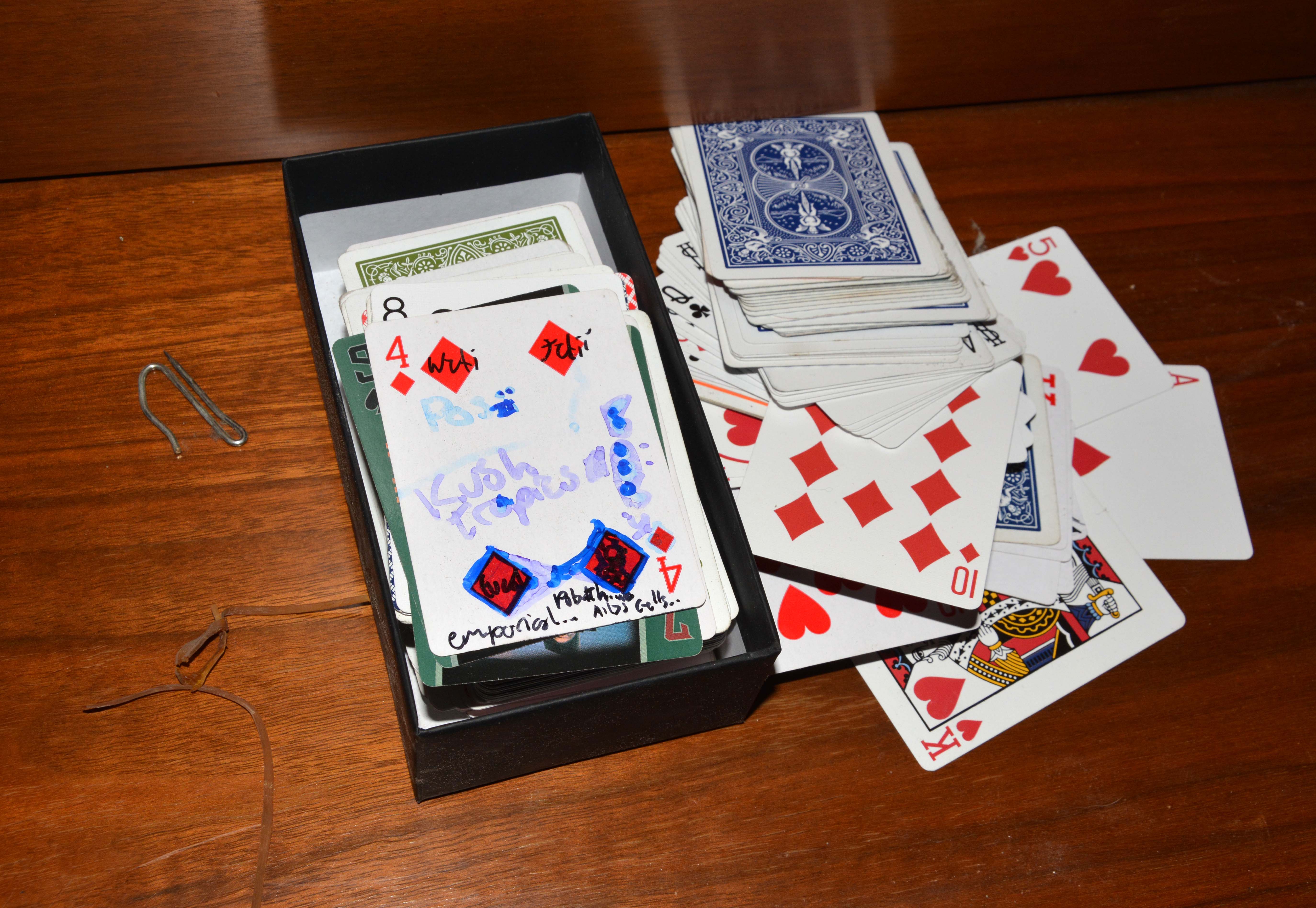
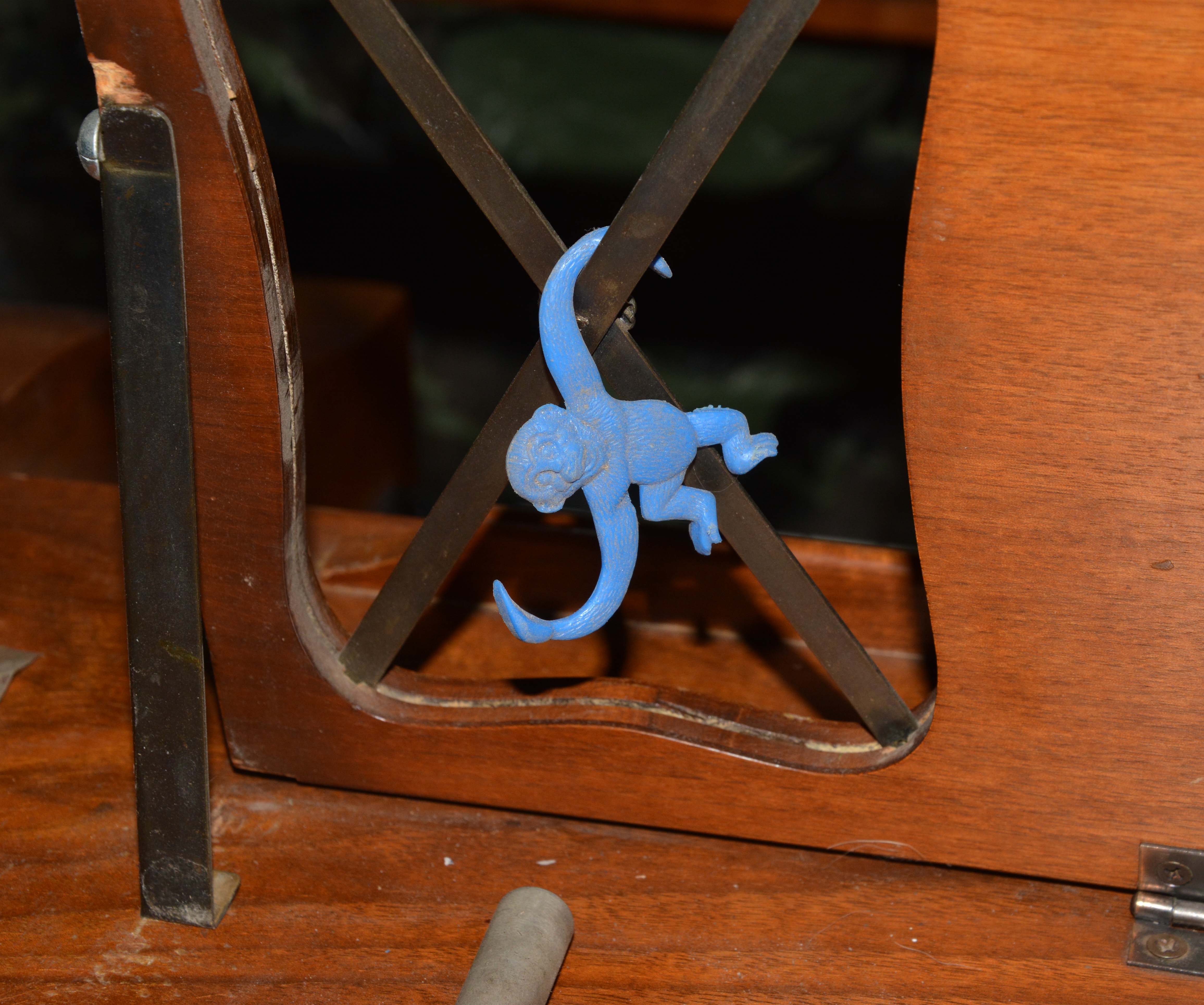
Inside behind the generator chassis were some strange things that I don't remember finding while at Lazaro's. These included a blue plastic monkey, a metal curtain hanger, and about 5 packs of loose playing cards, many of which had stoned gibberish written on them.
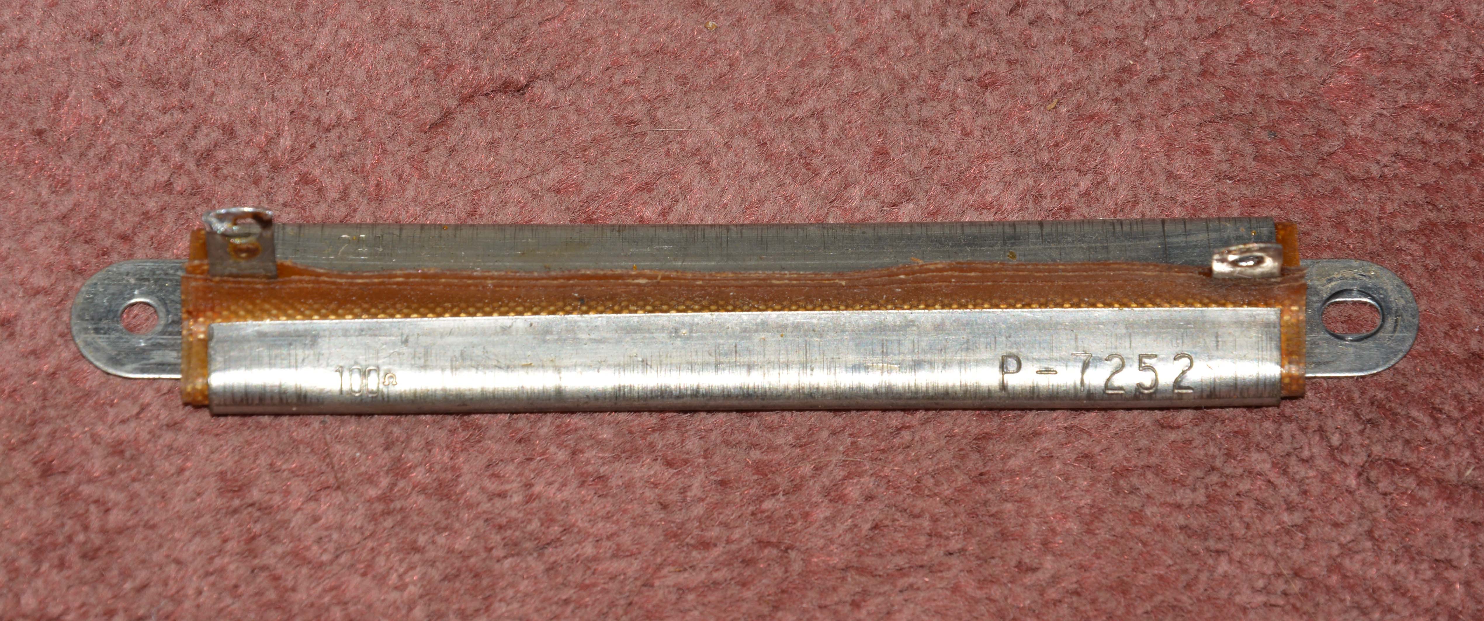
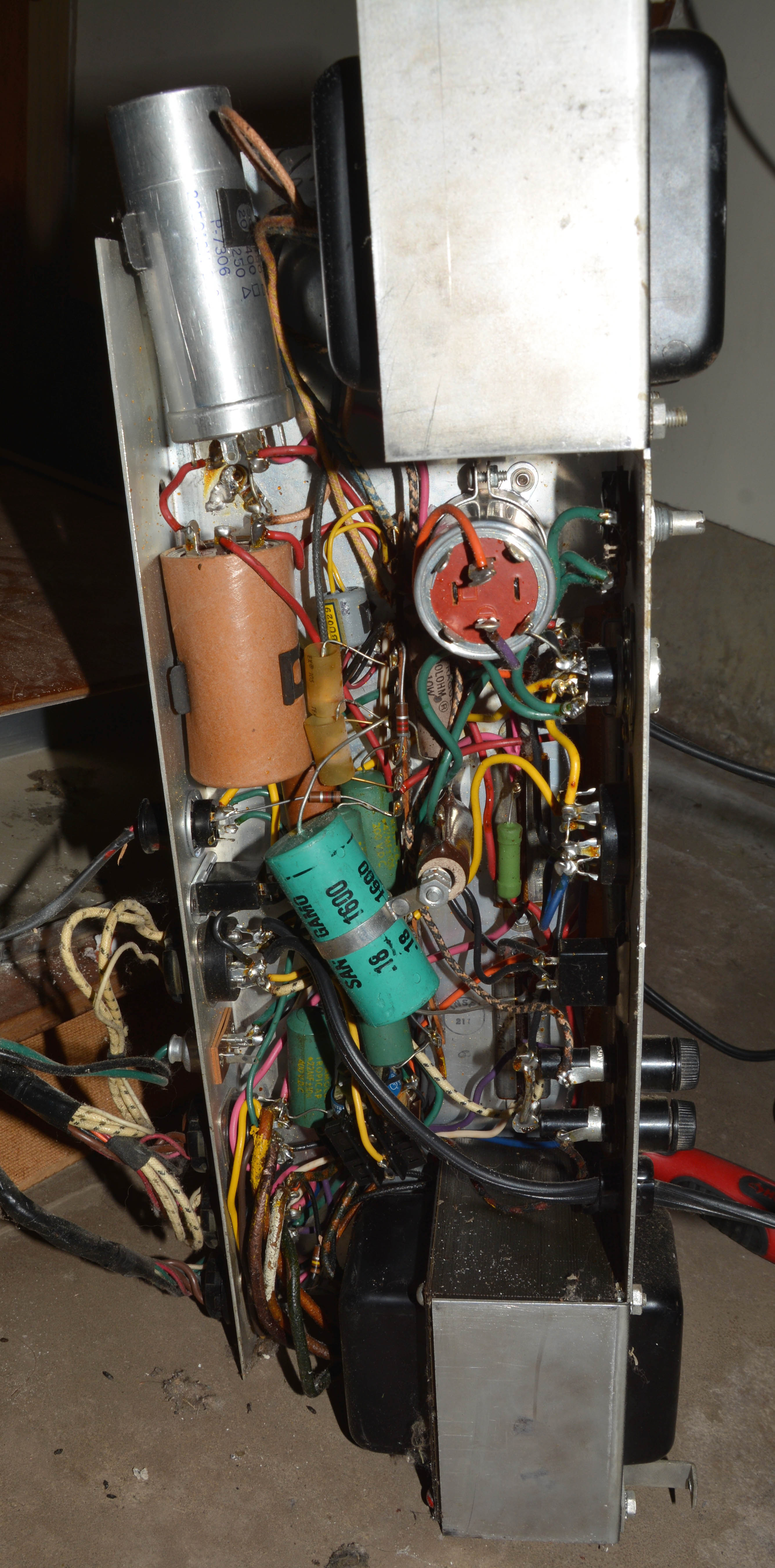
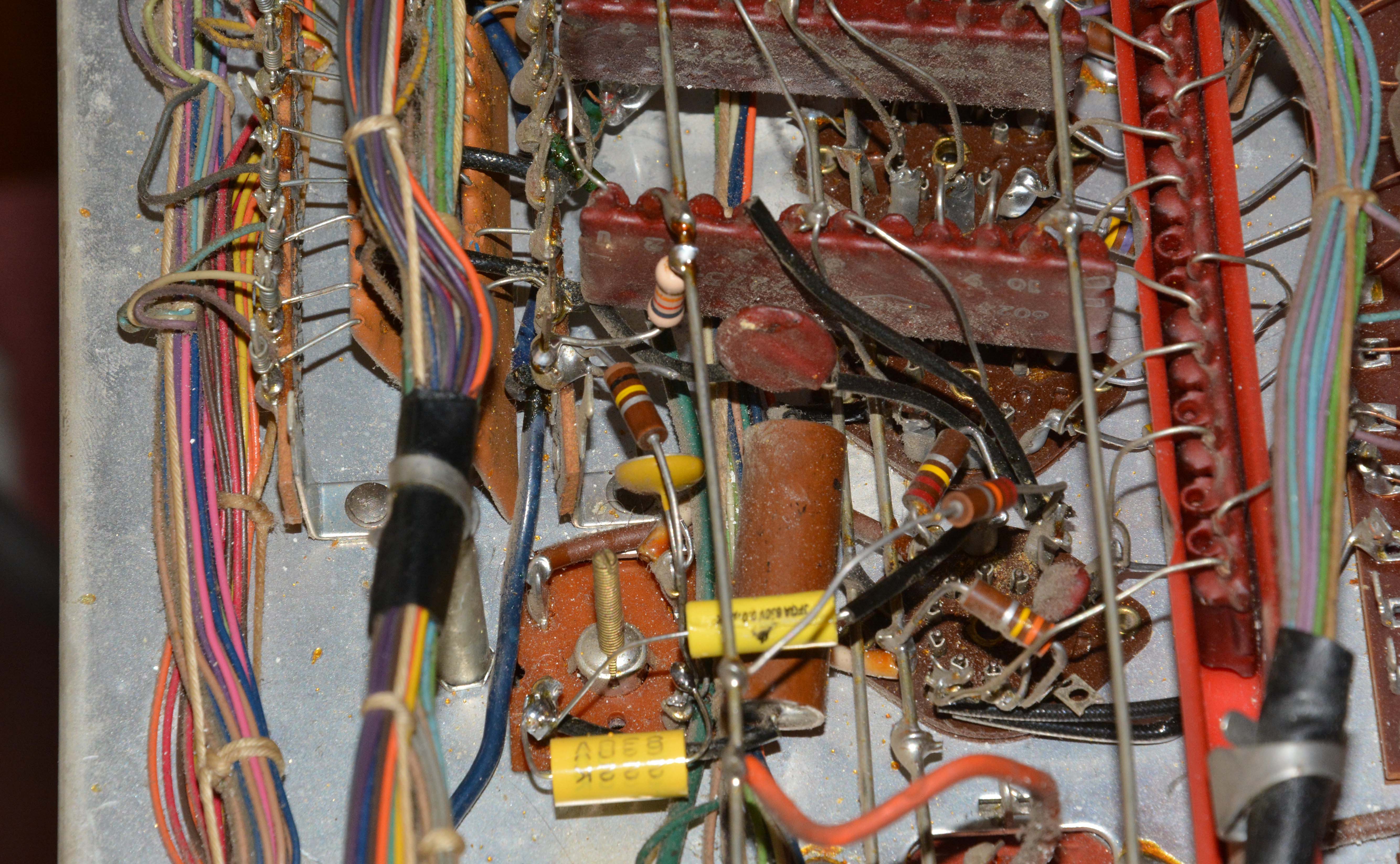
It is always a good idea to check for things like this in instruments so old and abused! Once all the detritus was removed, it was time to get to work. RepairsEspecially if you have your own FL or other tube organ in need of repair, this section may seem daunting at first. However, I want to stress that all of the repairs described were easy to perform, and required no special tools, parts, or techniques; even my vibrato modification is quick and simple now that it has been devised. All you need are basic screwdrivers, test equipment and soldering gear, generic inexpensive parts, and an approach of real troubleshooting (not willy-nilly parts-changing). There are high voltages inside tube devices, but these are of very little danger to careful people. To make the personal risk virtually nil, wear rubber gloves and long sleeves. Nothing beats the serviceability of all-discrete hand-built devices! They just tend to have many small problems accumulated over more than 6 decades, which previous owners did not bother to fix as they appeared. With proper care, these instruments can last for generations. Bad Candohm-style resistorsWhen I received the FL, it was functionally dead, producing no sound whatsoever from the speakers. It is always a good idea to check the fuses, especially before powering; although the two on the power supply chassis had been carelessly swapped, they were intact, so I put them back properly. The power lamp glowed, and so did the tube heaters. The next check was for high voltage (i.e. B+) from the power supply, with the aid of the schematic. I found that the 420V node, from which many B+ voltages in the instrument are derived, measured zero volts. This was caused by an open 100Ω 20W “Candohm” style resistor, shown below left. It was very obvious checking the two terminals; one end measured well over 400V, yet the other showed zero, and the resistor was not heating whatsoever, so no other possible failure existed. The relevant power supply section is shown in the middle, and the chassis itself is on the right below.
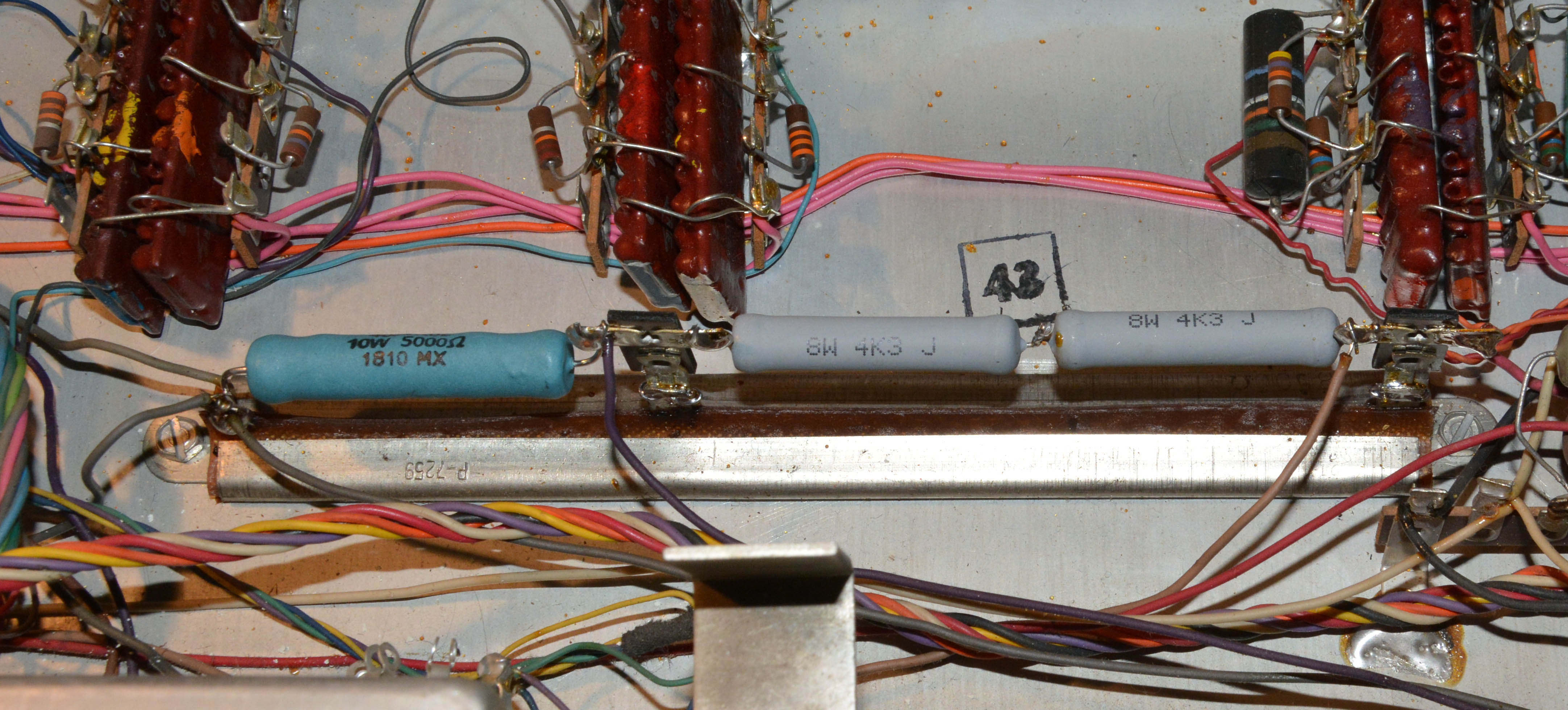
These "Candohm" or "Muter" style resistors fail often in Lowrey tube organs. Besides this one, two more were bad in this FL alone, another was bad in my "Holiday" LS, and I've read about many others online. They do not fail because of excessive power dissipation; in fact, they are usually rated for over twice the power that they actually dissipate, and will sometimes remain intact even when they do dissipate too much power. Instead, contact is lost between the resistive wire and one or more of the lugs, perhaps due to oxidization, or from the wire breaking for mechanical reasons. Anyway, replacing this 100Ω resistor (and reinstalling the tubes, see the next section) woke up the instrument considerably; it produced sound, with most stops, keys, and other functions working, and it was even in decent tune with no adjustment! Yet, there were still issues. At first, the STACCATO and SUSTAIN tabs worked OK, but after testing for a few hours, the STACCATO tab would no longer turn off its mode (as evidenced by no relay noise), thus disabling the sustain functionality too. This was easily traced to another open Candohm resistor in the “quality control” chassis, this time a 2-section unit of 5k and 8.5kΩ. The first section is just a voltage dropper prior to relay coils, and the latter subs in for the staccato relay coil when the mode is enabled (the coil is shorted out in this case). Below you can see my replacement, which is mounted on top of the original two-section resistor by means of attaching insulated terminals to two of the original lugs, and using the third as-is. I did this just in case the old resistor "unopens" somehow. Again, this resistor clearly did not fail by overheating, and this was confirmed by the fact that all voltages tested fine after resistor replacement.
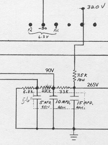
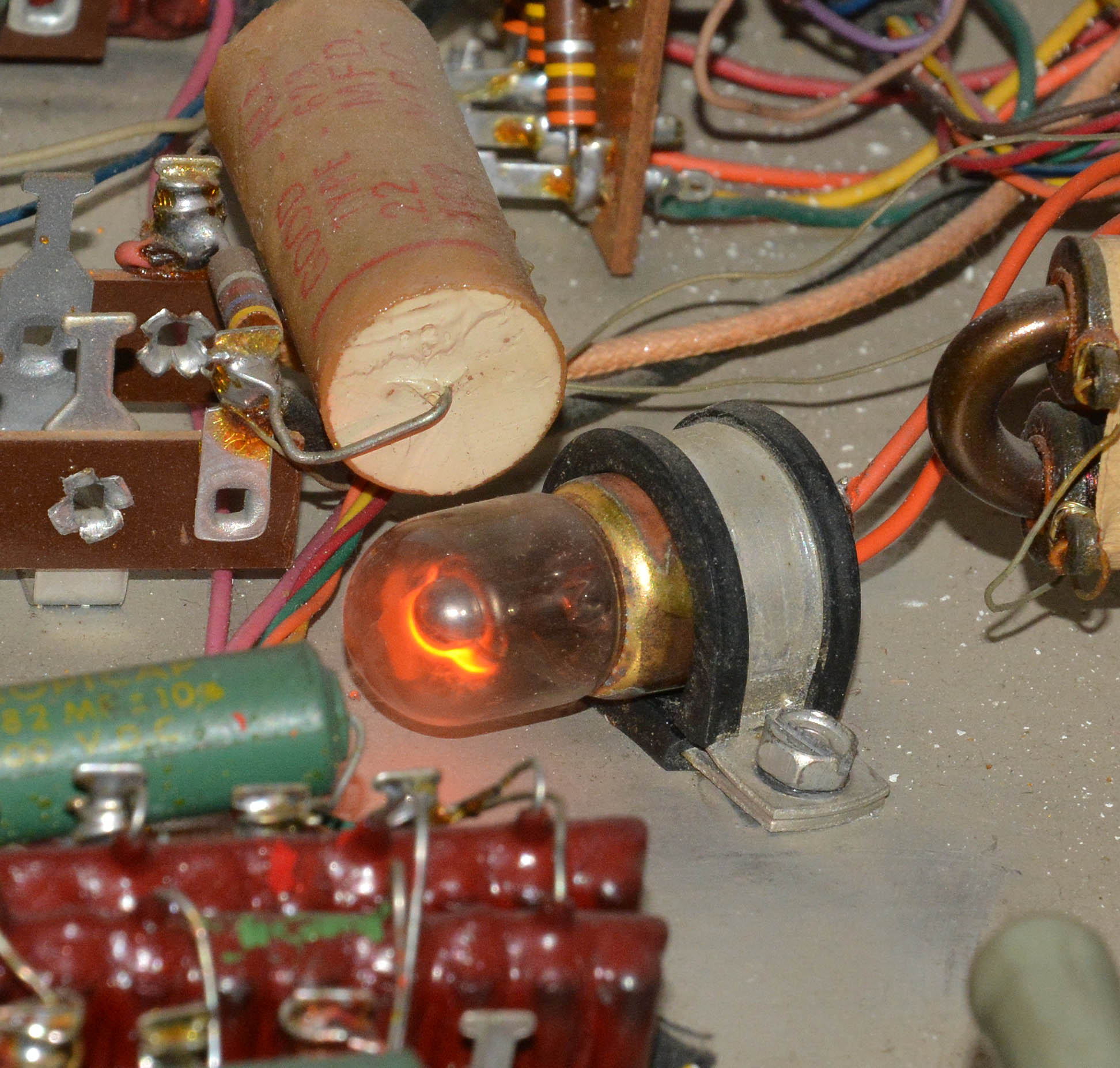
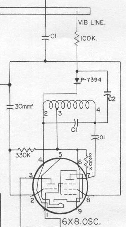
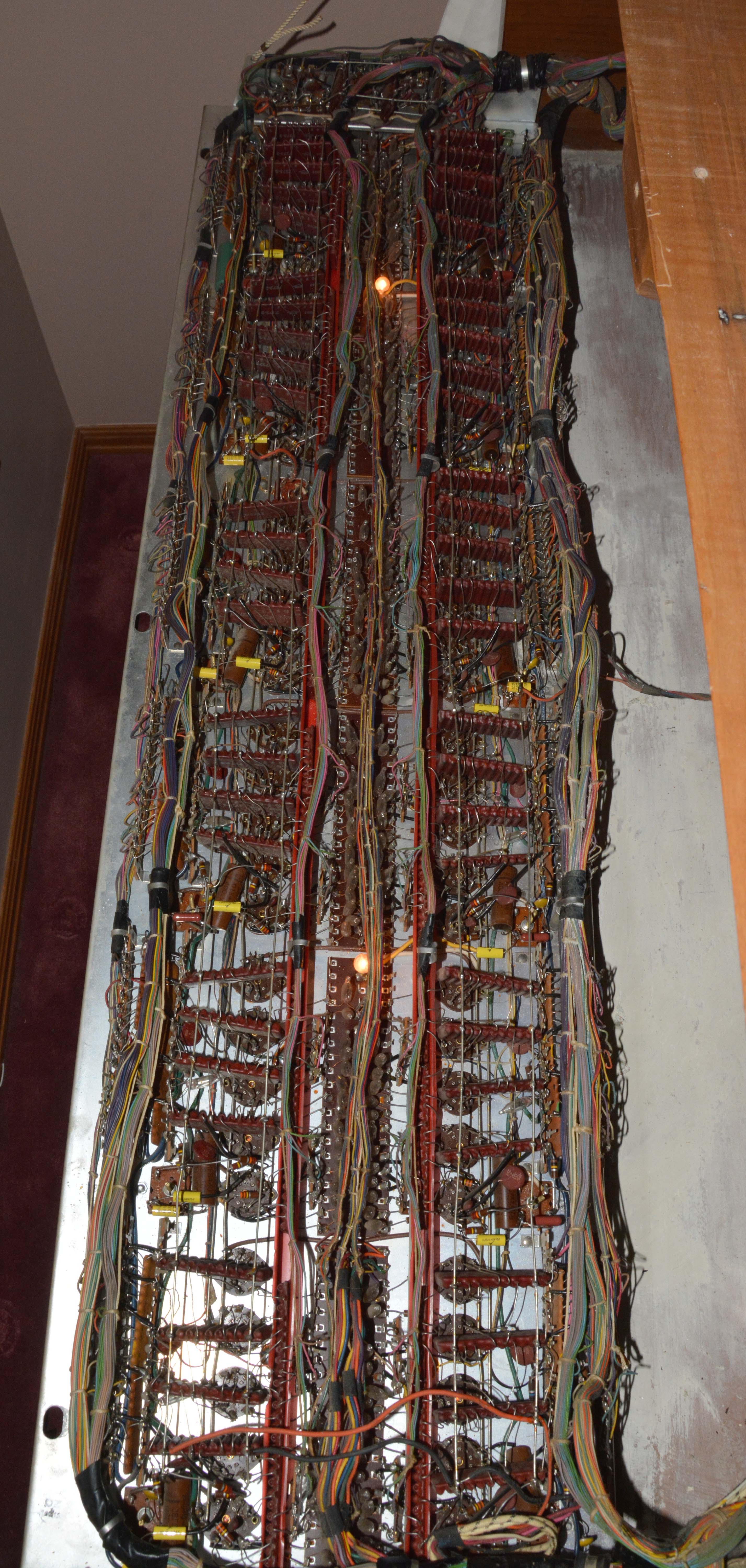
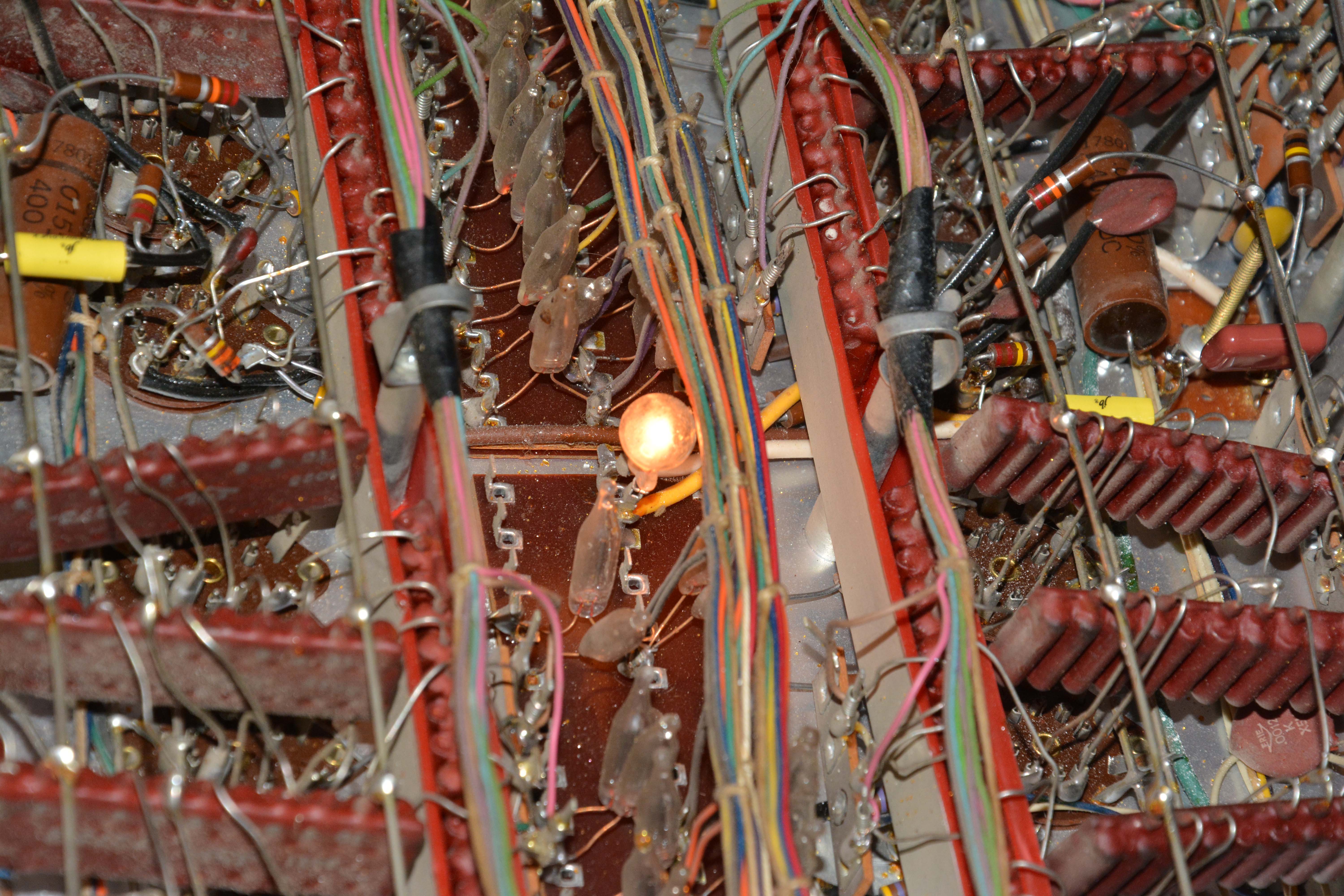
Since it is easy for me to fix things as they go bad, I left the remaining Candohms in place. However, if you were to perform a true electronic restoration on a Lowrey organ, all Candohm resistors should be replaced preventatively. I did this in my Lowrey LS. Also, in situations where the value is not written on the resistor and schematics are not available, you may be able to find such info in this partslist on the now-defunct Organ Service Corporation website. Bad tubesAs mentioned earlier, I had removed most of the tubes while the FL was still at Lazaro's Music. Before reinstalling them, I decided to test them all, and found a few bad ones, including one of the 12AX7s from the quality-control chassis, and a few generator-chassis 6X8 and 6FH8 types. It so happens that the 6X8 is one of the cheapest tubes, and I obtained a few dozen used ones online for about a toonie each including shipping. The 6FH8 is rarer, since to my knowledge its whole intended use was in Lowrey organs. It is a dual-section tube, the first being a triode, and the second being a tetrode with three anodes! However, they are still easy to find, and usually cheaper per unit than 12AX7s. In the end, I bought the remaining stock of 6FH8s from Murray at Harmony Repair, a friendly and helpful guy who is, I believe, the last "old-timer" organ repairman in Edmonton. He also told me some useful tips on fixing other issues with the FL, and info on tube organs in general. One of the four 7189 tubes in the power amp tested bad. Original 7189s are uncommon and expensive, especially in matched quads. However, the Soviet equivalent of the 7189, which is the 6P14P-EV / 6П14П-ЕВ, is both common and cheap, including in matched quads, so I used those. They take awhile to warm up, but sound fine, and most importantly, they can withstand the high plate voltage used in the circuit (420V). Note that normal 6BQ5 / EL84 tubes should not be used, since their rated maximum plate voltage is 300V. The organ can also be run with only a pair of output tubes, at the expense of halving the maximum loudness. I should also note that the amp section uses a 7199 triode-pentode as a preamplifier. Like the 7189, it is a rare and expensive tube. However, there are two cheap and easy solutions: either buy a base adapter to convert the common and cheap 6U8/6GH8 to the 7199's pinout, or rewire the socket itself for the 6U8/6GH8. Weirdly, a 6U8 is also already used on the amp chassis as a driver for the ECHO output channel! In LONG SUSTAIN mode, the organ “played itself”By this, I mean that percussive ciphers of random notes sounded quietly and repetitively in the swell-manual 8', 4', and 2' registers (i.e. those with sustain keying). In STACCATO mode, the rate of repetition became much faster. This video of an FL on YouTube demonstrates the behavior well. The cause of this problem was a faulty NE-48 neon lamp, used as a shunt voltage regulator in the 90V power supply circuit. This circuit is located in the middle-right of the Quality Control chassis (looking from the front), and is shown in the schematic diagram FL-4A, an excerpt of which is shown below. However, in the schematics, it shows a purely resistive divider chain of 7.5k, 33k, 22k, and 6.8k to ground, while in my instrument I found the chain is 7.5k, 33k, then the NE-48 bulb, then 4.7k to ground. The right image below shows the bulb itself, after performing the fix I am about to describe.
When my FL exhibited the problem, the 90V supply measured about 109V. I decided to reverse the lamp wires, since because the lamp is powered from DC, only one of the electrodes was worn-out, as evidenced by blackening on only one side of the glass envelope. Sure enough, this brought the voltage down to approximately 98V at first, at which point the problem was gone. Initially, the neon flickered and the voltage swung around a bit, but after a few hours, it stopped flickering, and the voltage stabilized at about 88V. Perfect! If reversing the lamp doesn't bring your voltage down sufficiently, and you cannot source one, another option would be replacing the lamp with a 22k resistor (and maybe replacing the 4.7k with 6.8k), returning to the design in the schematic. Yet another option would be to use a Zener diode, but that would be no fun at all, would it? For anyone wondering why this problem arose, it is because in SUSTAIN mode, the 90V supply is connected to the "off" bus of the great-manual keyswitches responsible for swell-to-great coupling. Each contact spring is joined through an NE-2 bulb (with series current-limiting resistor) to a corresponding "separate off" contact of the swell-manual 8'-4'-2' keyswitches. The voltage on the upper-manual contact springs (which normally contact their corresponding "separate offs") is the keying control voltage; above a certain threshold, the electronic keyer (comprised of a tube element and a neon-bulb gate) begins to pass signal, and loudness increases with voltage from there on. This threshold is lower in LONG SUSTAIN mode as compared to MEDIUM, because of lower bias voltage applied to the collector lines of the neon gates. Now, even with proper 90V on the great-manual "off" bus, there is a tendency for the coupler neons and sustain capacitors to behave as relaxation oscillators, since the firing voltage of NE-2 bulbs is often below 90V. The coupler neon fires, charges the sustain capacitor to roughly 40V (i.e. 90V minus the extinguishing voltage of the neon), then the sustain capacitor discharges through its parallel 22MΩ resistor until the coupler neon reaches firing voltage again, and the process repeats. This is normally of no consequence, since the voltage on the keying line never exceeds the signal-passing threshold. However, with the 90V supply almost 20V too high, and the low threshold of LONG SUSTAIN mode, the peak keying voltage is high enough to exceed said threshold, thus giving repetitive percussive ciphers! With STACCATO mode enabled, the sustain capacitor is no longer in circuit, and so the repetition rate is much faster. For more of an explanation of the keying circuit, see the "Electronic Design" section further down. On the upper manual sustain registers (8’, 4’, and 2’), sometimes, at the start of a keypress, all pitches would sound at onceThis happened sporadically whenever STACCATO was off, but could be consistently observed right after disabling STACCATO. The reason for this problem was that the “staccato relay” was successfully bridging the sustain capacitors together, but not connecting them to ground reliably. Without the ground connection, whenever one capacitor charged, it would charge through the others rather than through ground, briefly keying all other notes. Of course, this illustrates why a 61-pole relay is used, with the sustain capacitors (one for each pole) normally isolated from one another, rather than tying all the capacitors together and just using a single-pole relay to ground them. Speaking of the relay, here it is:
This type of relay is very easy to disassemble, with only two nuts to get the top plate off. One of the lock-washers was missing, indicating someone had fiddled with the relay before. In any case, I cleaned its contacts with isopropyl alcohol on cotton swabs (especially the two ground contacts, which were sooty). I also bent the ground contacts upwards, since they were bent too far down for whatever reason. This fixed the problem. Below shows before and after. What a beautiful component! What ever happened to things being round?
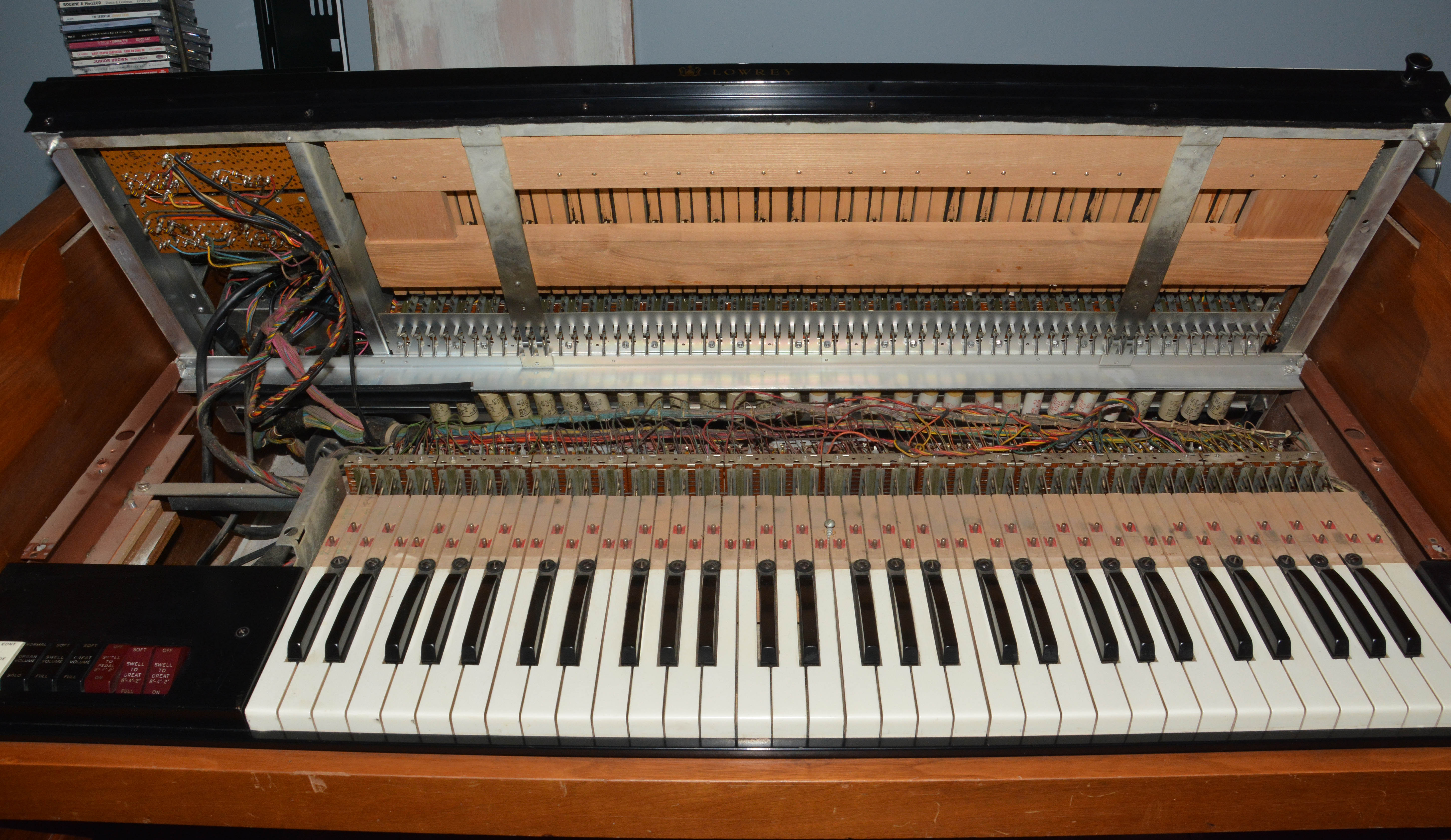
You may wonder how to access the relay, or in fact anything below the quality control chassis. Firstly, the back panel must be removed by various screws. Then comes the top panel, firstly extracting the vertical screws holding it to the rear support beam, then sliding it out from the back. At that point, you can access the swell-manual contacts simply by hinging upwards the quality control section, like so:
It really is that easy, since the chassis is hinged at the back and held by clips towards the front. The swell manual also hinges upwards in exactly the same way, though make sure to put back the quality control section first:
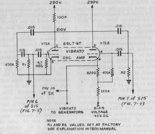
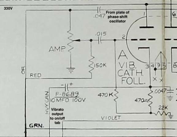
This makes it possible to access the great-manual keyswitches, as was necessary in the next repair described. Phenomenal ease-of-service, and beautiful build! Some upper manual notes sustained even with SUSTAIN off (and STACCATO off)Several notes had this problem, caused by poor contact between the swell-to-great coupler springs (on the great manual) and their corresponding “off” bus. In order for the sustain capacitors to be discharged quickly when SUSTAIN and STACCATO are off, this contact must be made. In some cases, cleaning with Electrosolve was sufficient, but in others the problem was not cleanliness, but a lack of physical contact entirely. This was fixed by bending the key’s actuating rod slightly downwards, bringing the spring into firm contact with the off bus. A general rule is that a key should bring forth sound when it is depressed about halfway. Bad vibrato waveformAfter playing for awhile with vibrato on, I noticed that the effect sounded strange. It was asymmetric and unnatural, like "eeeeoweeeeow", rather than a nice "eeaooaeeaooa" as normally expected (and as exhibited on my Lowrey LS); this was especially noticeable when SLOW and HEAVY. In other words, the frequencies of the master oscillators were not being modulated sinusoidally, but rather with a narrow pulsed wave. Yet, all components of the vibrato circuit tested OK; even the capacitors turned out to be mylar film rather than paper, and thus perfectly within spec and without measurable leakage. It turns out the design is flawed in multiple ways. Firstly, the designers basically copied the vibrato oscillator/buffer circuit from previous models, yet changed its output from directly-coupled to capacitively-coupled without redesigning the buffer stage appropriately; this results in a pulsed waveform on the vibrato line. Secondly, the vibrato line is biased such that the modulator diodes are normally non-conducting; this makes for pulsed modulation even with a perfect sine on the vibrato line! Thirdly, due to imperfect waveshape of the phase-shift vibrato oscillator and its passage through multiple high-pass stages, the resulting waveform is unacceptable even once the first two flaws are fixed. Let's look at the oscillator/buffer circuit. Below shows the FL circuit on the left, and S/SS/DS circuit (as shown in the Electronic Organ Handbook) on the right.
While the S/SS/DS' drawing is clearly more refined, upon inspection the circuit is mostly identical. The oscillator itself is a typical phase-shift type not worth explaining here. In both cases it precedes a cathode follower acting as a buffer, which is biased via a cathode resistance tap. There are some trivial differences, including that the bottom of the S/SS/DS' cathode resistance ties to 45V instead of ground, supply voltage is about 10% lower, and the tube is the older octal 6SN7 type instead of the miniature 12AX7. The 0.22µF capacitor from cathode to ground on the FL can also be ignored for now, as it has little effect. Now for the major difference. On the S/SS/DS, the cathode follower's output connects directly to the vibrato line, and hence to all vibrato modulator diodes, which are integral to the master oscillator tubes, and which each have 270kΩ in series for current-limiting and isolation. The triode is biased such that its cathode (and hence the vibrato line) oscillates about 75V; with the cathodes of the diodes held at 45V, the diodes remain forward-biased throughout each vibrato cycle, and thus constantly draw current through the cathode follower. There is a 0.22µF capacitor from the vibrato line to ground, but it has no effect except in terms of the Glide function. Since current is always drawn (and assumedly never reaches the tube's saturation level), cathode voltage follows grid voltage almost perfectly, and thus vibrato modulation is more-or-less sinusoidal, thereby sounding natural and pleasant. The 8.2kΩ and 150kΩ cathode resistances serve only to furnish grid bias voltage. On the FL, however, there is a 1µF coupling capacitor between the cathode follower and the vibrato line, and the cathode resistances comprise the entire "pull-down" or "current-sinking" capability of the stage. The FL's vibrato diodes are silicon, and with 100kΩ in series instead of 270kΩ, presenting a stouter load than the previous vacuum diodes and resistors. As well, the vibrato line is biased with a 22kΩ resistor to the 45V supply (which itself connects to all vibrato diode cathodes). You might think this results in 45V bias on the vibrato line, and thus diode conduction for only about 50% of the cycle. The reality is even worse. Look at the master oscillator:
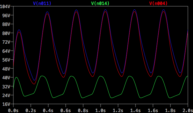
What classic type of circuit is formed by C2, the vibrato diode, and the tank? A clamper! Oscillations from the tank are coupled through C2 to the diode, which clamps the positive peak at about 45.7V. The remaining waveform is shifted downwards, effectively giving a DC offset well below 45V, thus pulling down on the 100kΩ resistors, thus bringing the vibrato line voltage below 45V. In my actual instrument, I measured the 45V line at 38.3V (no problem), and the vibrato line at 29.2V, which is nearly 25% lower! So, let's fix the problems one at a time, starting with the cathode follower. Below shows an LTspice simulation of the original circuit. An ideal sinusoidal voltage source replaces the phase-shift oscillator for now. Red trace shows grid voltage, blue trace shows cathode voltage, and green trace shows vibrato line voltage.
Notice that the cathode and vibrato-line waveforms are actually sinusoidal except when the grid voltage drops below the cathode voltage. Why does this divergence occur? Simply put, because the cathode resistance cannot "pull down" strongly enough to preserve the waveshape. The triode can only "pull up", after all. For deeper analysis, let us ignore C2 again, since the bulk of the effect comes from C1, and also let us consider the vibrato line to be an AC ground. See how the cathode waveform is nicely sinusoidal during the entire rising portion of the input? During this portion, the tube conducts appropriate current to keep cathode voltage in perfect correlation with grid voltage. At the peak, C1 is charged to virtually the same max voltage seen at the grid. On the falling portion of the input, since the tube cannot discharge C1, it must instead discharge through R14 and R15. For a short time (while grid voltage is higher than the natural discharge curve of C1 through R14/R15), the tube remains in conduction. Soon, however, grid voltage drops below the C1-R14/15 discharge curve, and the tube stops conducting. Cathode voltage then exhibits exponential decay typical of R-C discharge, diverging more and more from grid voltage until the start of the next cycle. This type of distortion is called slew-induced distortion; the cathode follower circuit is too slow (i.e. its slew rate is too low) to amplify the input signal without error. Despite this, the cathode waveform doesn't look too bad; it would sound just fine if it were used for vibrato modulation directly. However, it is passed through C1, which forms a high-pass filter along with the twelve parallel sets of resistors and diodes; cutoff frequency is about 20 cps. High-pass filtering will always make a bad sinewave worse, and indeed, the result is practically a sine with a severely clipped trough. On an oscilloscope, the real waveform was even more detestable, looking like a lumpy positive pulse for roughly 1/3 of the cycle, followed by a more-or-less flat bottom for the rest. So, my cathode follower modification involves three steps: decreasing cathode resistance, biasing the grid independently, and removing the extraneous 0.22µF capacitor. A proper cathode resistor should be small enough to ensure the tube always conducts even at maximum input frequency, while not so small that the tube saturates on the positive peaks of the waveform. I found that replacing the 150kΩ resistor with 47kΩ satisfies both conditions. Then, to bias the tube, I decided to install a fixed voltage divider: 6.8MΩ from grid to plate, and 2.7MΩ from grid to ground. These values give proper bias (for about 80–90V on the cathode) and practically the same signal level at the grid as before. Yes, they may seem rather large, but they are not too large for a normal 12AX7. Self-biasing results in significant distortion, so I avoided it, and of course, I bridged across the 8.2kΩ cathode resistor and removed the original 470kΩ grid resistor used for self-biasing. To fix the incorrect vibrato line bias, I first removed the 22kΩ resistor from vibrato line to 45V. Then I installed an 82kΩ resistor from the vibrato line to the generator B+ line (180V). In my instrument (with 45V rail measuring 38.3V), the result was 44.0V bias on the vibrato line (5.7V higher), giving conduction throughout each entire vibrato cycle even in HEAVY mode. Of course, all oscillators required re-tuning after this, since DC current in the vibrato diodes detunes the oscillators—this is how the Lowrey Glide works, after all! Overall the tuning may be marginally less stable than before, but probably more stable than in Lowrey's usual direct-coupled arrangement, where the emissions of the cathode-follower triode affect vibrato line bias, and hence overall tuning; emissions change over time as the tube ages. My LS, which uses direct coupling, is stable enough to only require tuning once every half-year or longer. As of August 2021, the FL has remained in good tune since I performed this vibrato mod in August 2020. Lastly, to fix the still-unacceptable waveshape (with narrowly peaked positive and negative excursions), I first substituted the 0.015µF capacitor from the plate of the phase-shift oscillator to the "AMP." control (and also the ON/OFF and LIGHT/HEAVY tabs) with 0.22µF, conveniently using the one removed earlier. Also increased the amplitude control to maximum. This greatly improved the waveshape at the grid of the cathode follower by reducing highpass action, but with the consequence of increasing signal level considerably (though not enough to cause distortion in the cathode follower). To compensate for this, I added a 100kΩ resistor in series with the cathode follower's 1µF coupling capacitor. This reduces the signal reaching the vibrato line appropriately and also creates lowpass action with the 0.22µF vibrato-line-to-ground capacitor. Finally, vibrato sounded good! To summarize the modifications:
Pictures of the finished mods:
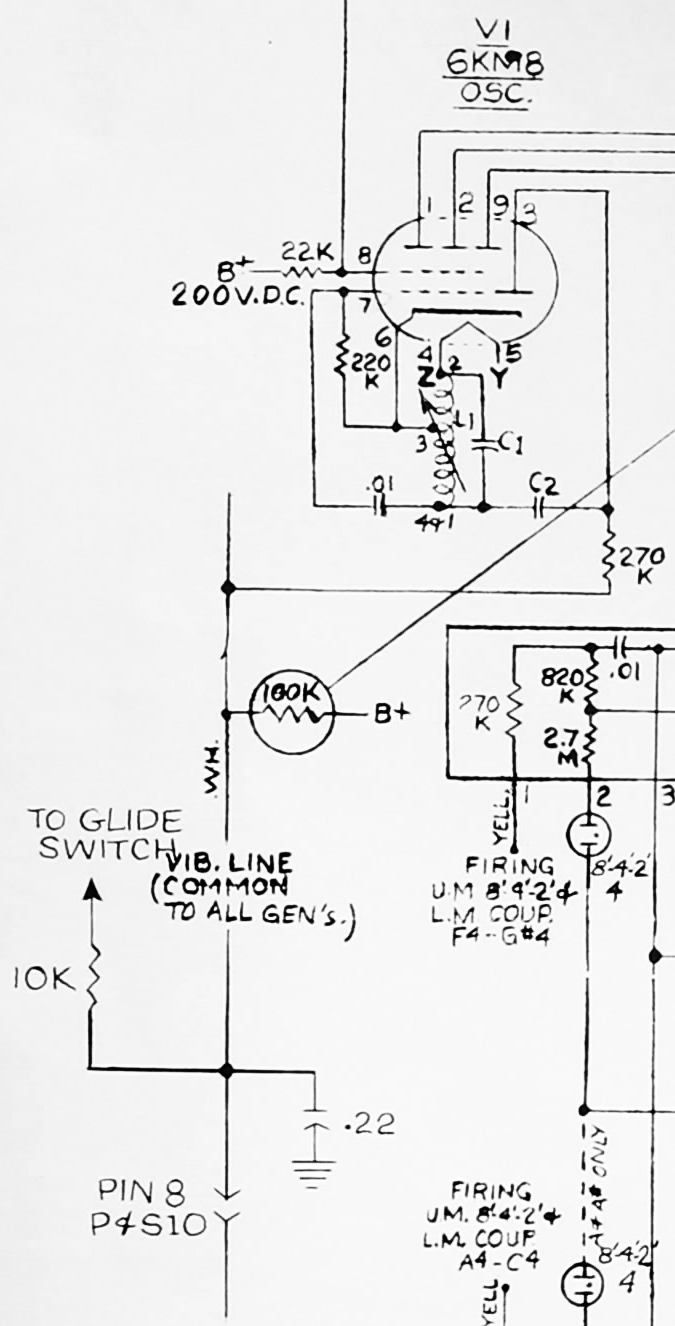
Besides the FL, CN, and CH, I am not aware of other models having quite the same flawed design, but then again, I haven't seen every Lowrey organ schematic. As of August 2021, I discovered that some other models use silicon diodes for vibrato modulation, including the DSA and SS-25 at least. Their cathode followers were redesigned appropriately in the same way as the "Heritage Deluxe" DSO from 1962 shown below, yet the vibrato line still seems under-biased, which would cause pulsed modulation. Strange! Now, you may wonder why Lowrey used silicon vibrato diodes in these mid-period high-end models: it is to allow the 6X8 oscillator tube's triode to be used for keying. On cheaper and older Lowrey models, there are only two sustain registers (8' and 4') and hence two keying elements needed, thus the triode can be wired as a vibrato diode. But on these more elaborate organs, there are three sustain registers (8', 4', and 2'), so that's not possible. Eventually (in 1962, I believe), Lowrey started using a special tube called the 6KM8, which was probably developed at their behest. It has three plates for keying, plus a built-in diode for vibrato; it is like the 6FH8 except with a diode section instead of a triode, thus freeing up a pin so that the heater and cathode connections are separate, which is necessary for the oscillators but not the dividers. Late-period high-end models such as the DSO, FLO, CHO, and SSO-25 use this tube, and they do everything right as far as vibrato is concerned. Below is the DSO vibrato circuit:
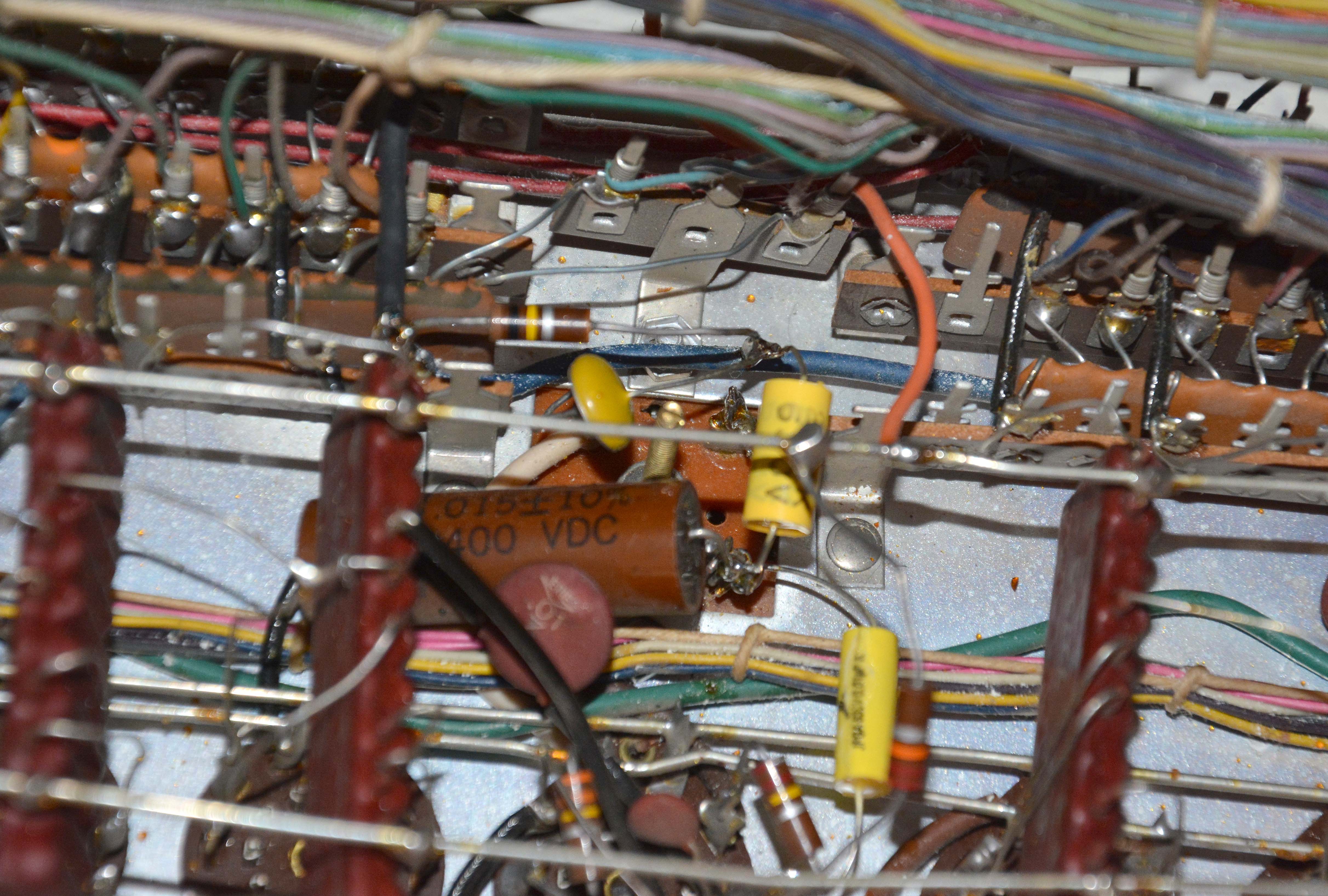
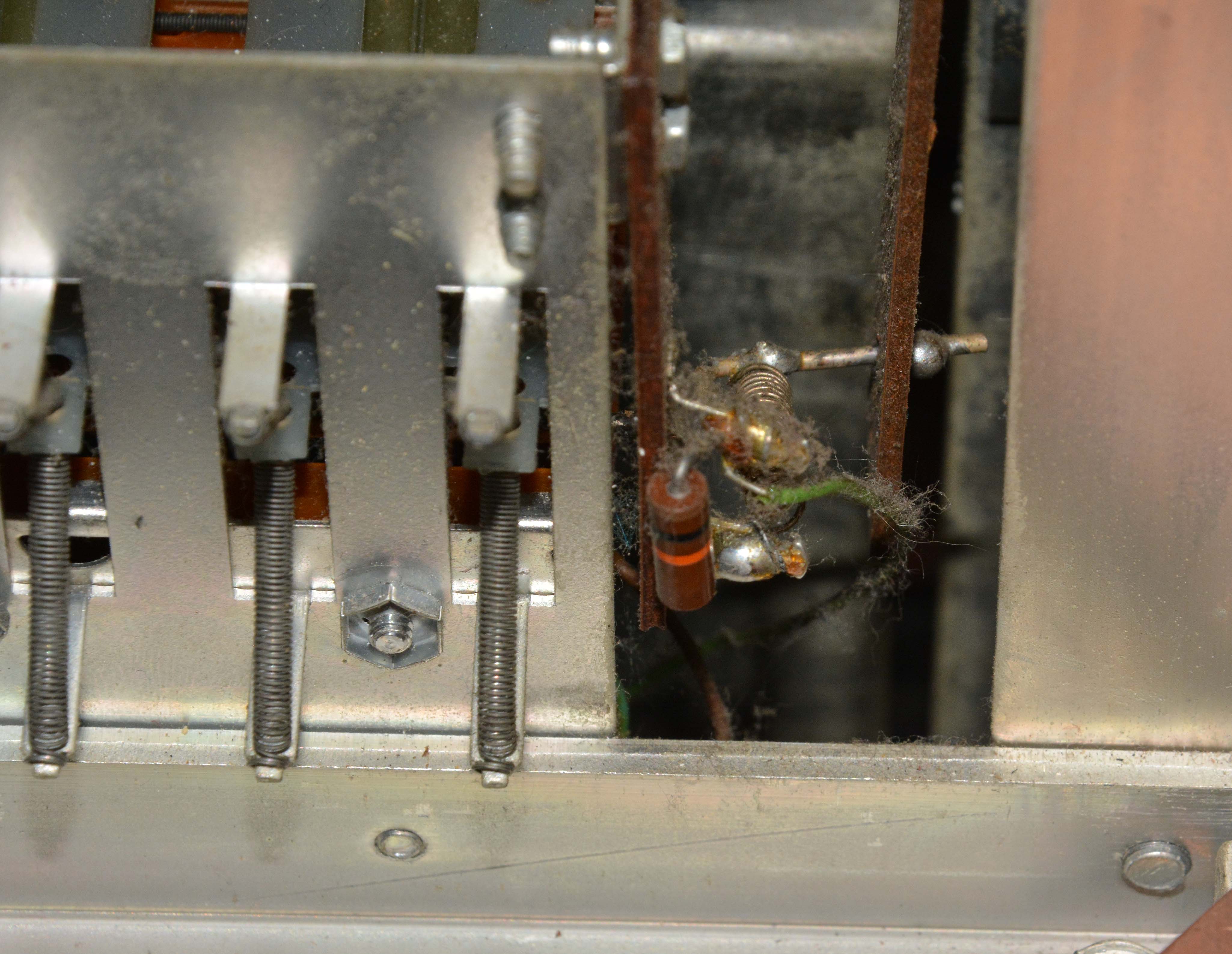
As seen, the DSO's cathode follower has very low cathode resistance to drive a massive coupling capacitor: 10µF. The diodes are hollow-state, and the vibrato line is biased positively relative to the generator bias line via 100kΩ to B+. The coupling cap to the amplitude control is much larger (reducing highpass action), and the amplitude control is a voltage divider instead of a shunting rheostat, so that waveshape does not degrade with amplitude reduction. Probably capacitive coupling was used to improve tuning stability. Intermittent detuning & weak vibrato on one oscillatorI noticed this odd problem on the C oscillator after fixing the vibrato waveshape. Pushing on the oscillator coil (or other oscillator components, especially vibrato-related ones) resulted in a slight detuning and loss of vibrato depth. First suspecting an intermittently bad vibrato part, I checked the 100kΩ resistor and vibrato diode; both good. Then I noticed that all vibrato components mount to a fourth terminal on the tapped inductor; this terminal exists for convenience, with no supposed connection to the coil. Yet, after removing all parts mounted to it, I found that pushing it a certain way caused it to develop about 40kΩ resistance to the coil! So, given the difficulty of disassembling the inductor and the good rigidity of the three vibrato parts, I simply mounted them with their shared node in mid-air away from the bad terminal. Below shows a picture; apologies for the softness, caused by my forgetting to narrow the aperture.
No CHIMES functionThe CHIMES drawknob adds extra pitches to a 1.5-octave range of swell-manual keys, simulating the overtones of bell chimes. This worked properly at first, but failed after I messed with the drawknob mechanism. The function is enabled by rotating a busbar with bent sections, such that extra contact springs touch it only when the bends protrude upwards. It is supposed to be energized with reduced keying voltage, so that the extra tones do not overpower the main note. I found that the busbar was being rotated, but was not receiving any voltage, since the solder joint on the fixed end of the voltage-providing spring was cracked. Resoldering it fixed the problem. Below shows the mechanism, and the cracked joint prior to resoldering.
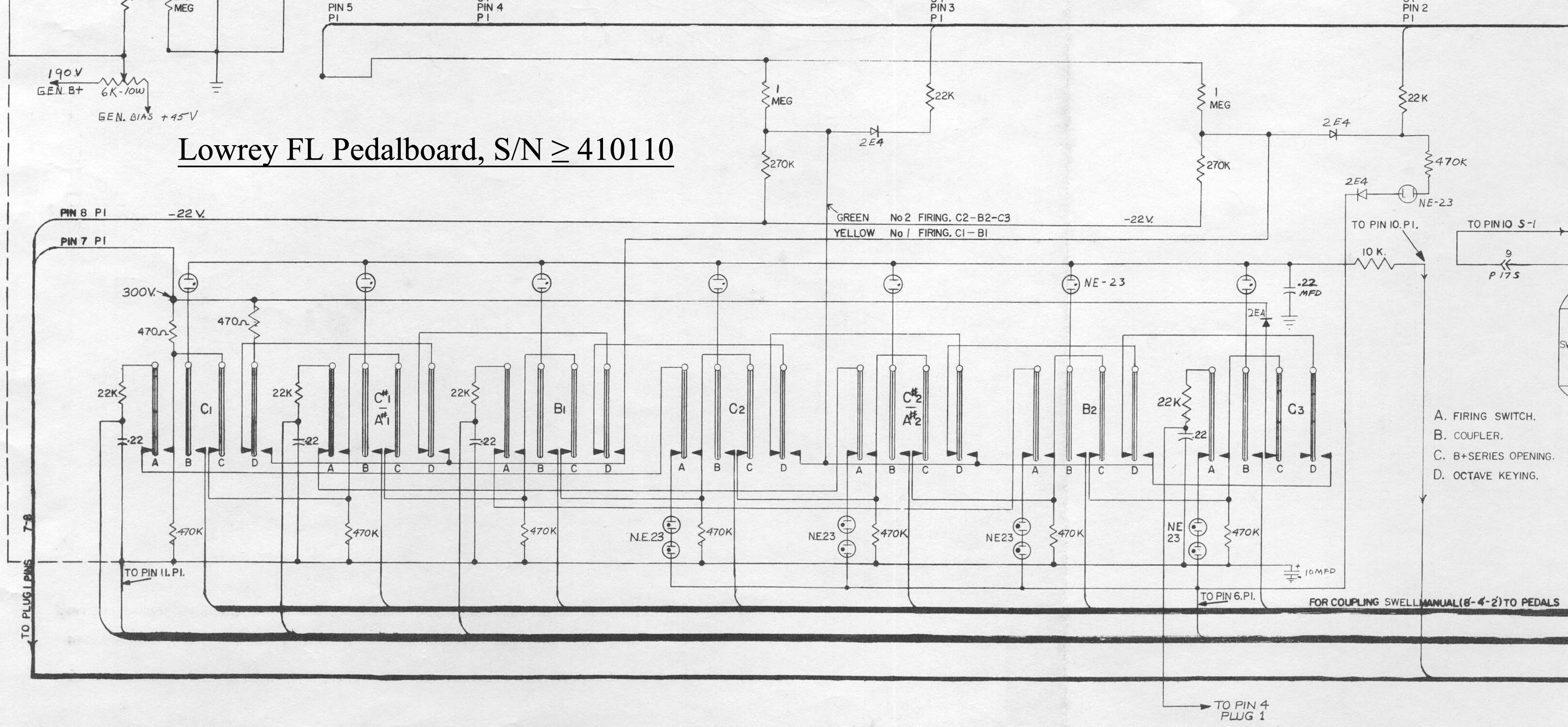
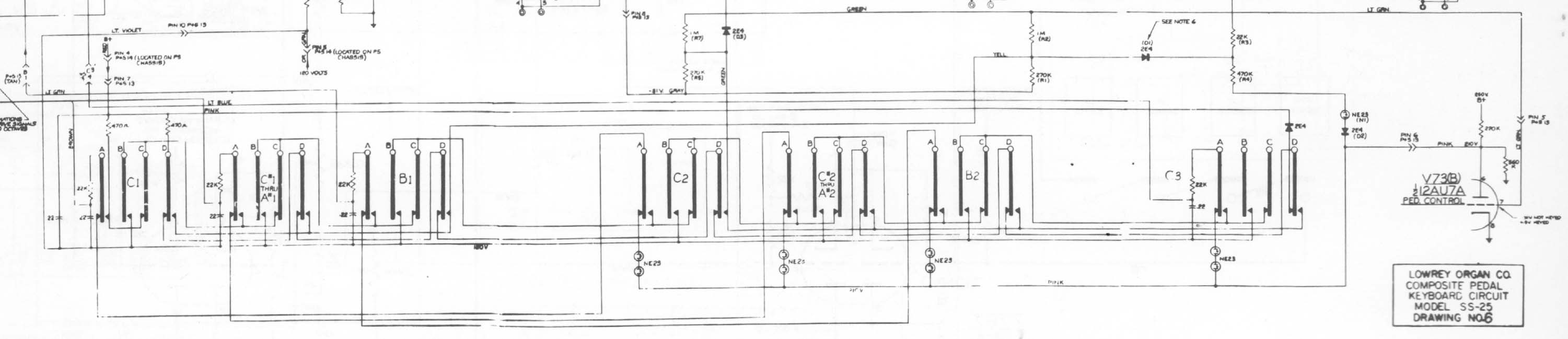
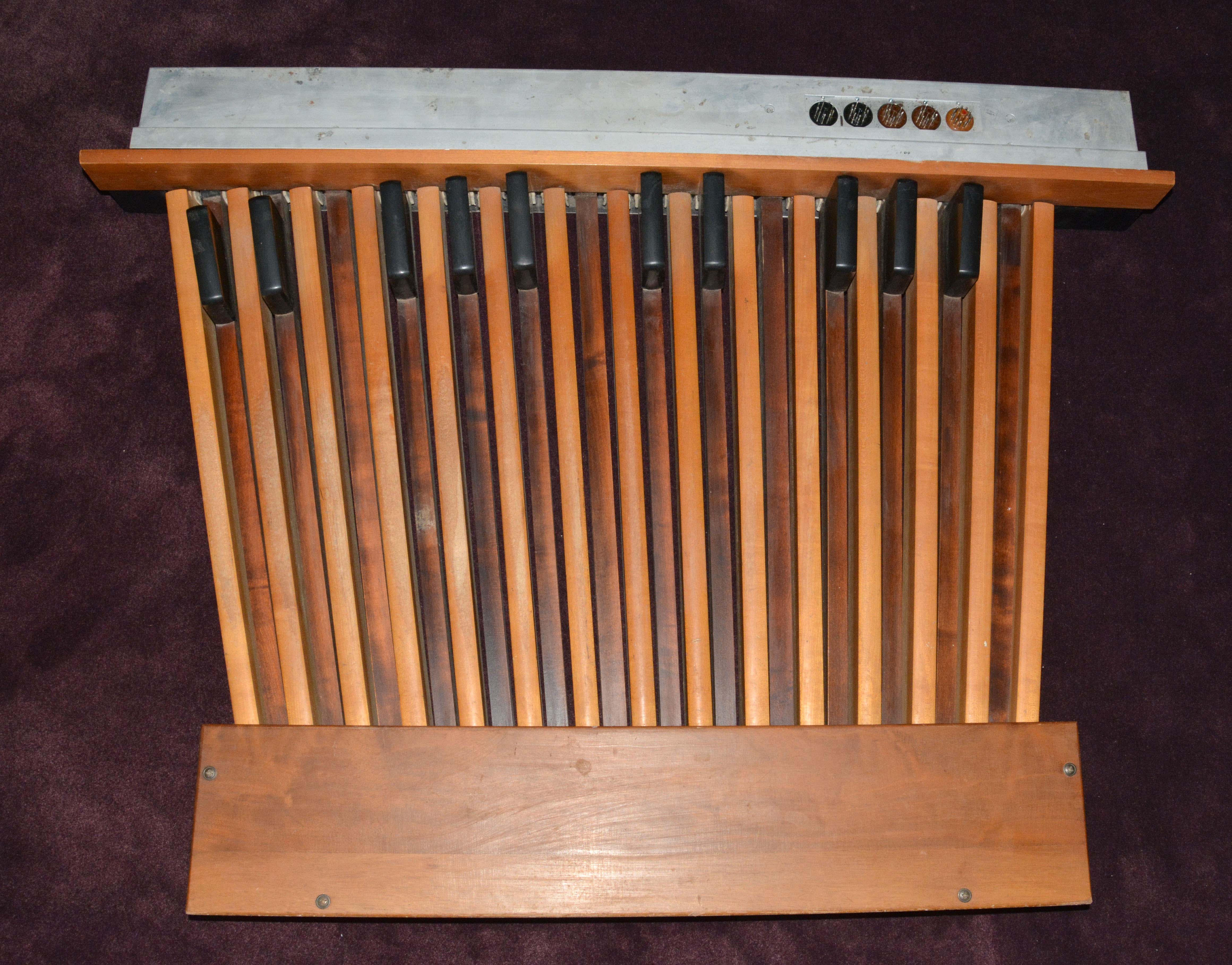
Sticking keys at the bottom of the great manualThis was caused by a bend in the metal retaining channel at the front of the keys. To fix this, I had to detach the whole manual assembly and slide it backwards slightly. There are four large bolts that hold the assembly to the wooden cabinet from below; two are easily accessible from the outside, while the other two are within the cabinet and not so easy. Place a box or something inside the cabinet to hold the assembly up at the back, so that it doesn't tip down when pushed backwards. Anyway, once those four bolts were out, I gently slid the manual assembly back, then pulled forwards on the bent portion of the metal channel. This bent it away from the keys, eliminating rubbing. Then I put the manual assembly back in place. You can see in some of the above pictures that the keyfronts still have black paint on them from significant playing (not by me) while the fault existed. Detached tab switch felts (adapted from my Lowrey LS article)A simple problem with a simple fix, but worth mentioning, since it seems to affect all tube Lowreys, and can have bad consequences if left alone. Some of the felt strips underneath the rocker tab switches had come unglued. It was quick and easy to reattach them with PVC-E glue, my usual favorite for felts. In some cases, if a felt moves out of place, the switch springs can travel too far and bridge across the two throws. On my FL, this happened once on a switch with significant voltage between the throws, causing a large spark and a pop in the speakers. The metal panels surrounding the rocker tabs can be removed by two screws each, at which point the felts can be checked and fixed if needed. A proper restoration of a Lowrey organ would include completely regluing these felts. Missing pedalboardThis instrument's original 25-note pedalboard was lost and probably destroyed before I had any opportunity to acquire it. While most detachable pedalboards are purely mechanical devices that actuate keyswitches mounted within the console, Lowrey's tube organ pedalboards actually contain the keyswitches. In the FL's design, there are four switch poles per pedal, as well as various supporting components, and it connects to the console via five Amphenol octal-style connectors (one 11-pin and four 9-pin). This makes substitution and scratch-building rather difficult. Trying to find an original, I contacted several local shops and posted a request on the Organ Forum, but with no luck. In mid-2020, I set up a saved search on eBay for "Lowrey pedalboard", and this paid off in October when a unit showed up originally belonging to a "Lincolnwood" SS-25 tube model. This type of pedalboard has only two octal-style connectors (both 11-pin), since the SS-25 has no provision for swell-to-pedal coupling. However, the design is otherwise extremely similar to the FL, with the pedal switches having exactly the same arrangement of poles and throws, and with the vast majority of the wiring being identical. Sections of the two schematics are shown below; many thanks to "tucsondave" on the Organ Forum for scanning the SS-25's pedalboard schematic for me!
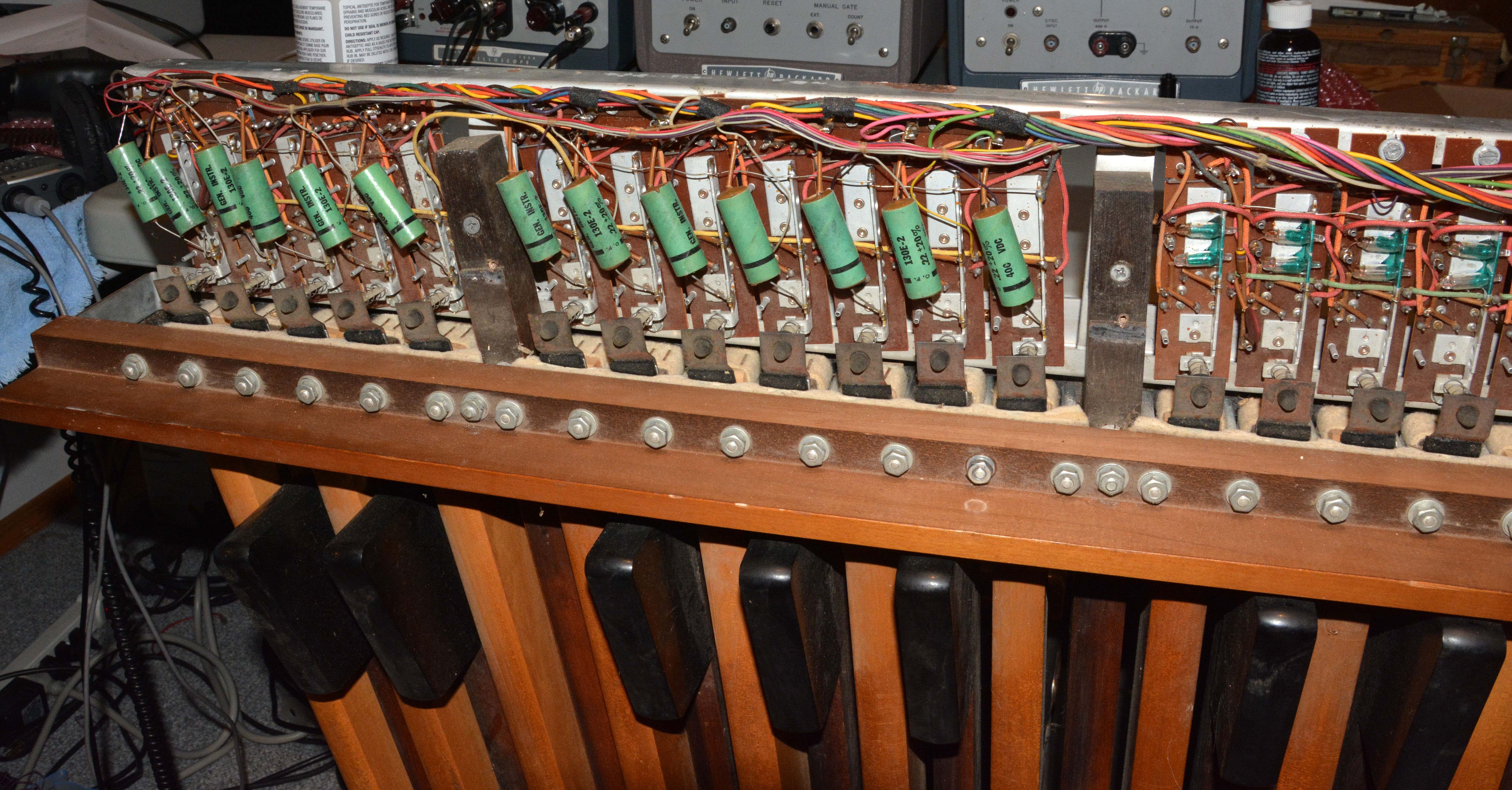
So, I bought the pedalboard. Shipping was expensive, and it was not packed well, but it arrived without serious damage. The original wiring is shown below:
I performed the necessary modifications to convert the SS-25 pedalboard into a proper FL version, including those required to add coupling. If I had not chosen to add coupling, less than half of the labor I performed would have been needed. Amphenol connectors were sourced from Pacific T.V., whom I highly recommend. Here are all the modifications I performed:
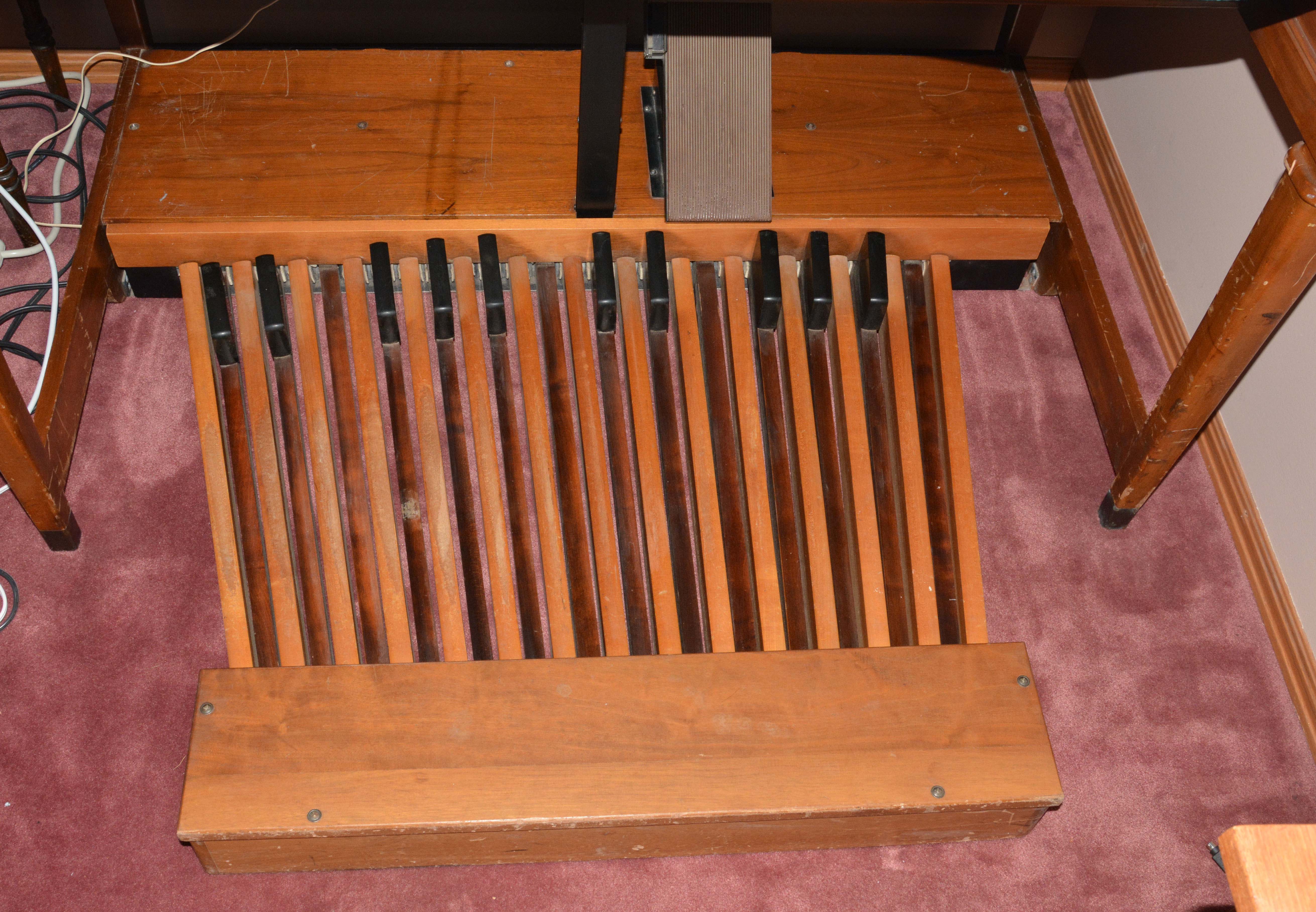
Also, I took some time to clear out dust, tighten many loose screws, and fix a crack in the wood of the rear portion. After everything was finished, I checked over my work, plugged it in, and... all the pedals sounded perfectly on the first try! Remarkably, I did not have to clean even a single switch contact, despite that the pedalboard was clearly damp and stored in dirty conditions for some time. The switch throws are thick metal bars that appear to be silver-clad, and the poles are flexible roundwound wire, much like typical low-pitched guitar strings. Now that is a reliable and serviceable vintage design. Here is the pedalboard after modification:
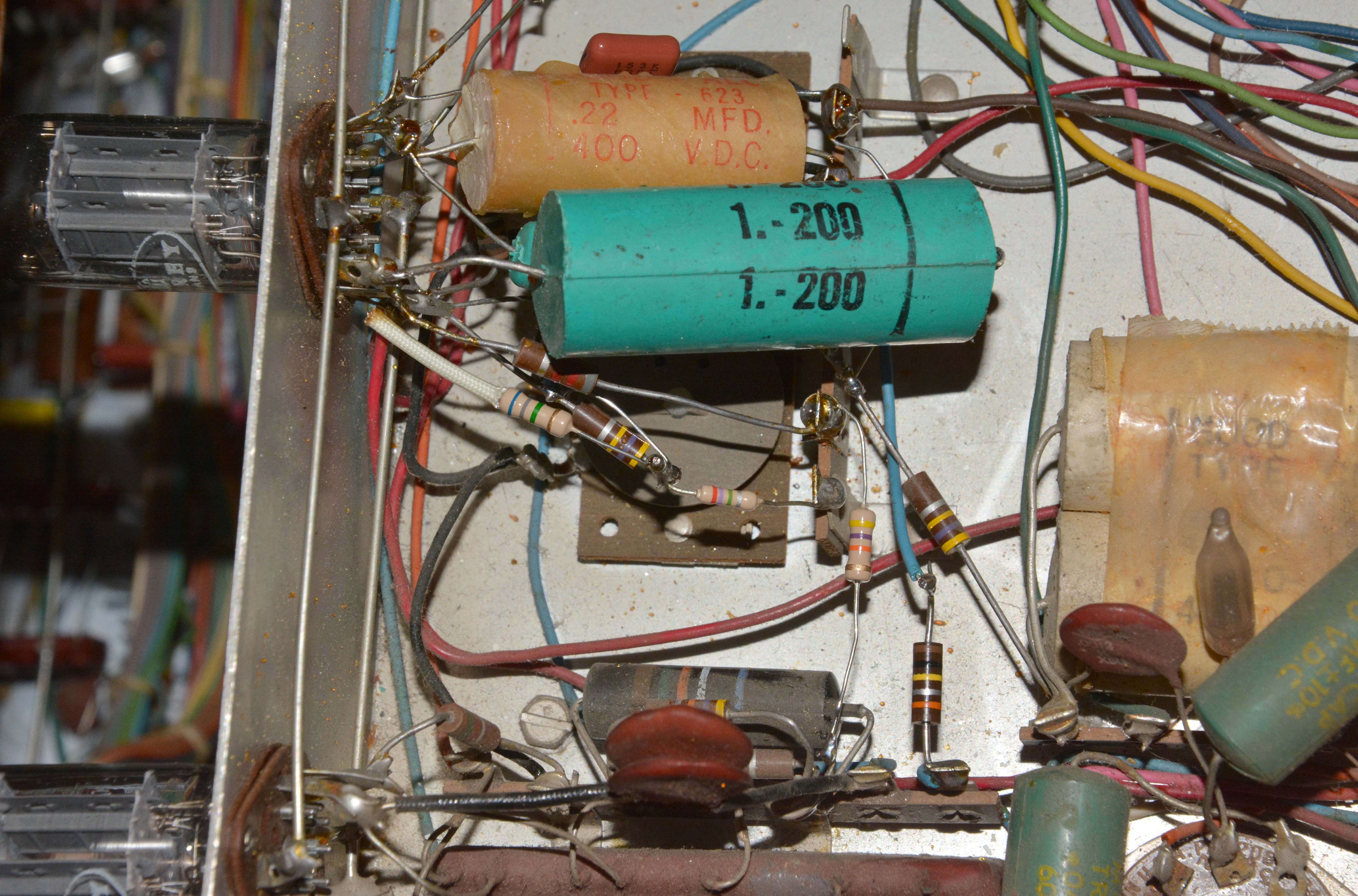
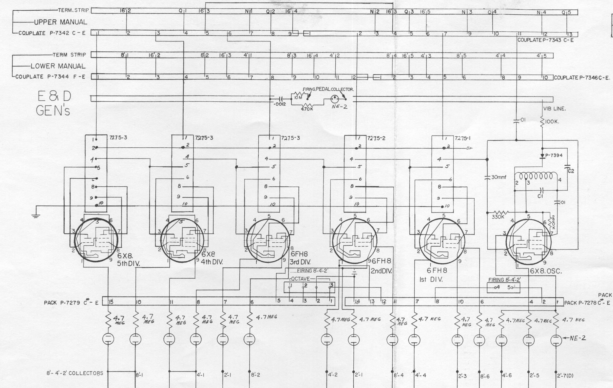
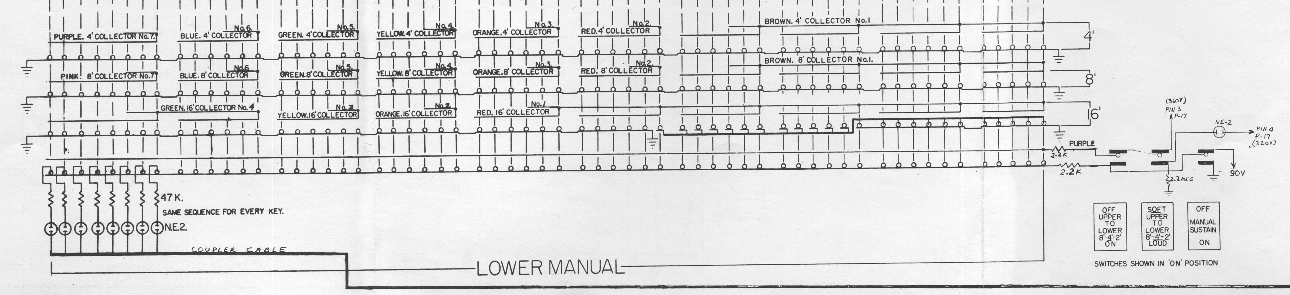
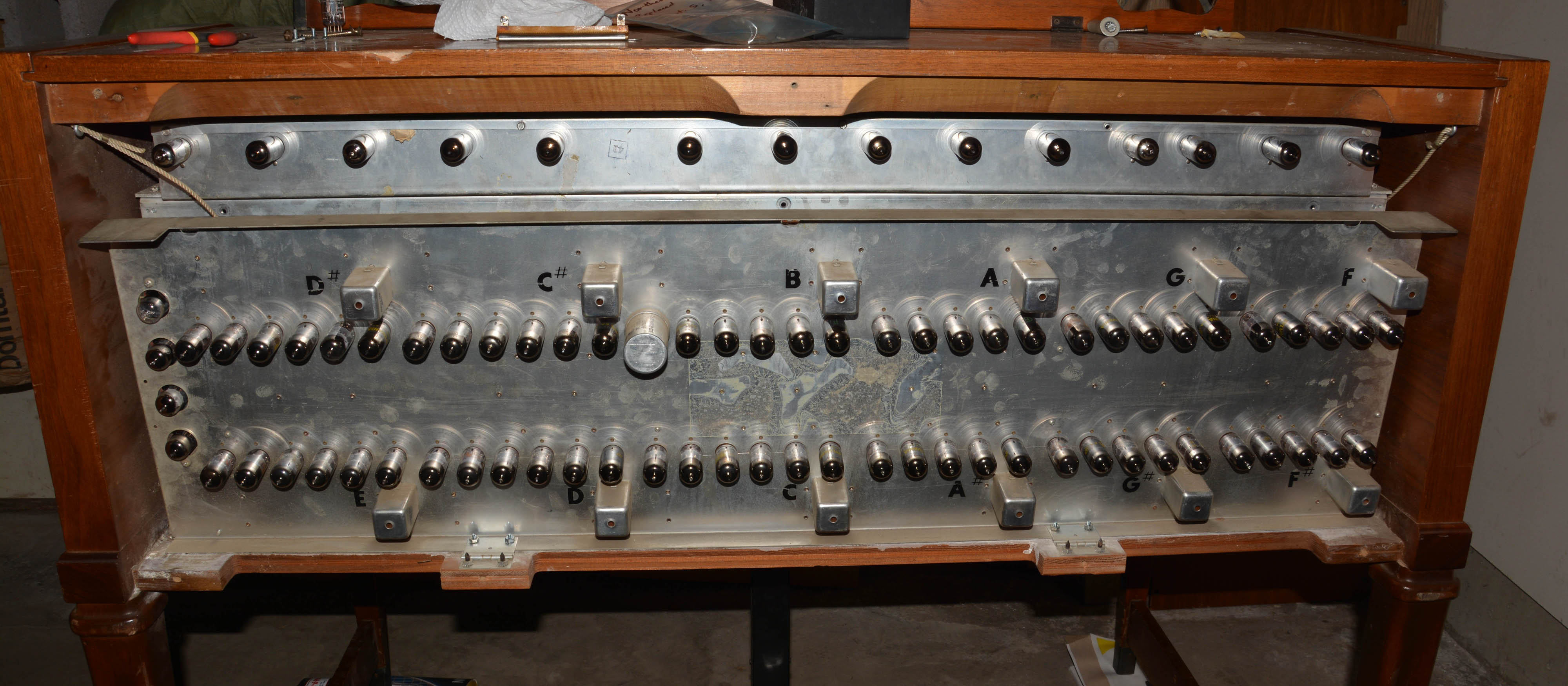
Last issuesWhile making the demo video, it occurred to me that the "doubler" coils seem slightly out of tune, since the doubling effect is not as good as the LS'. One day I may try fixing this, since the coils are easily accessible once the top panel is removed. You may wonder about capacitors. Well, I replaced the two-dozen "bumblebees" in the generator section, partly just to recoup costs while eliminating junk parts preventatively, and I replaced the 0.22µF vibrato-line-to-ground cap during my vibrato mods. Otherwise, the capacitors are all original. This inclues all electrolytics, and dozens of various tubular caps both paper and plastic-film; e.g. the green Micamold Tropicaps are paper (though quite reliable), while Sangamo 33M and Good-All 600UE types are plastic-film. See my article on vintage tubular caps. I haven't decided to do a proper electronic "restoration" of this instrument yet; for now, I just continue to admire the quality of the 60-year-old parts. Cosmetically, the main problem is that the great manual Clarion 4' tongue tab is chipped at the end. The Flute 4' tab is also imperfect, having been glued sloppily but securely after breakage years ago. So, if someone has replacements for either, I may be interested, though I don't want any of these organs to be scrapped unless they are truly ruined already, such as from flooding, infestation, or dropping out of an airplane. The Electronic DesignBecause Lowrey's tube organs share the same basic principles (and many specific circuits), I will refer you mainly to my Lowrey LS article, where I go into detail about its electronic design. However, there are some noteworthy differences. Lowrey's Festival schematics are not as well-drawn as those of the Holidays; for one, we do not get a "Tube Function & Tonal Flow Chart" for the FL as we do with the LSB. But of course, we can break the instrument into the usual subsections: tone generation, keying, tone shaping, amplification, transduction and power supply. Mostly of interest are the first three, so I will describe them. Tone generation and keyingTrue of all self-contained Lowrey tube organs, a frequency-divider system is used with Hartley master oscillators (producing asymmetric pulsewaves) and Eccles-Jordan dividers (producing squarewaves). Pitch classes C to E generate six octaves in all, while F to B have five octaves. Thus, there are 65 pitches continuously generated, going from C2 to E7 (65.41 to 2638 cps). Though this is a great improvement over the 36 pitches of the LS (which are not even enough for one manual's 8' register, thus giving rise to plenty of tricks), there are still insufficient pitches to cover the full spans of all pitch registers. To compensate for this, foldback and frequency doubling are used. Unlike in Lowrey's spinets, "solo" type frequency division is not used except in the pedal section. The master oscillators generate pitches F6 to E7 (1397 to 2638 cps), corresponding to the fourth-F to fifth-E keys in the 4' register. With the aid of doubling, the generator range is extended upwards by an octave, so the 8' and 4' manual registers have all pitches in full polyphony. While the 5 1/3' register would be complete if it used doubling, it instead uses foldback (or "repeat" as Lowrey calls it) on the highest 3 keys, so that the two highest 5 1/3' collectors can simply be doubled to give the highest 2 2/3' pitches, rather than having a separate highest 2 2/3' collector to avoid double-doubling the top 3 notes. The 2' register uses doubling for the fourth-F to fifth-E keys, then both foldback and doubling for the highest 8 keys (F to C), since doubling cannot be done twice. Foldback is also used for the lowest octave of keys in the 16' register; I find this rather disappointing, since I like to play basslines on the manuals, and the lowest pitch of C2 at 65.41 cps is more than an octave higher than the lowest audible pitch. Two types of keying are used: sustain and non-sustain. The swell-manual 8', 4', and 2' registers are in the former category, while all others are in the latter. Lowrey used two different sustain keying designs depending on the model, one of which results in "true" sustain (where loudness decreases from maximum upon key release), while the other gives a "reverb-like" sustain (where loudness quickly drops to a lower level upon key release, then decreases normally). The LS uses the former system, which I already described; the FL, however, uses the latter. One simple clue reveals the system used: models with "reverb-like" sustain have a STACCATO tab, while "true" sustain models do not. The first Lowrey model to use the "reverb-like" system was the "Lincolnwood" SS in 1957. Sustain keying is performed electronically, with the key contacts switching DC voltage, while in non-sustain keying, the key contacts switch the AC audio signals directly. In both types of keying, the resulting audio signals end up on collectors, which are firstly separated by pitch register, and secondly split into small groups of usually 6 notes each for the sake of flute filtering. You may wonder why they are separated by pitch register; this is so that each register can have different stops in use simultaneously (e.g. just Flute 4' and String 8'), which is not a trivial concern, as I will explain later when I write about my Conn 811 tube organ! Below shows the generator chain for the E and D pitch classes, and the others are nearly the same. The schematic is rather confusing, not least because the tubes are drawn the way the physical pins are arranged, rather than for good comprehensibility. As well, the diagram is incomplete, since much of the circuitry is contained within "packs" and Couplates that are simply shown as rectangles with pin numbers, and not diagrammed anywhere in the FL's schematics. Still, we can get a good picture of what is going on.
The master oscillator is a Hartley, quite similar to the LS' except in the fine details of how vibrato and glide are applied. C1 and a tapped inductor comprise the tank circuit, and the 6X8's pentode section is connected as a cathode-follower, with the cathode connected to the inductor's tap, the control grid biased via a 220kΩ resistor to the cathode, and the tank's oscillations coupled into the grid via a .01µF capacitor. The tank end closest to the tap is connected to one side of the heater, which itself is connected to a low-impedance "bias" node held around 45 volts (not shown). The plate and suppressor grid are not directly part of the oscillator; the screen grid instead acts as the usual plate, and from it, signal is taken for non-sustain keying and triggering of the first divider. The suppressor grid is used as another anode, whose purpose befits calling it a sustain keying element. When DC keying voltage is applied to this element from a keying line through a resistance, oscillator signal develops on it, then passes through high resistance and a neon bulb (which acts as a gate), in this case to the 5th 2' collector. The actual plate is unused here, but serves the same purpose in those instances where it is used. Note that the 6X8 triode's grid is fed oscillator signal, and its plate is used as another sustain keying element. In the F through C pitch classes (i.e. the majority), all three available elements are put to use. Vibrato and glide work on the same principle as the LS, but because the 6X8's triode section is used for keying instead of vibrato/glide modulation (where it would be connected as a diode), a type 2E4 silicon diode is used instead. Capacitor C2 is in series with the diode, and this series combination is placed across the tank circuit. Oscillation on the vibrato line results in corresponding oscillation of the diode's dynamic resistance, since (after my modification) the vibrato line is always biased positive relative to the diode's cathode (which itself connects to the +45V "bias" line). "Lowrey Glide" has two modes. In continuous ("CON'T.") mode, the vibrato line connects to 320V through 10kΩ when the glide button is pressed, causing the diode to conduct hard. Since the diode's dynamic resistance is lowest in this case (and so low that any oscillation on the vibrato line no longer affects pitch), C2 thus has its maximum effect on the tank's resonant frequency, and the oscillator's pitch lowers approximately a semitone and stays there until button release, at which point it drifts back up rather gradually, resulting in a pitch-bending effect similar to hawaiian-guitar or slide-trombone. In AUTO mode, a 10µF capacitor and extra 10kΩ resistor are placed in series with the aforementioned 10kΩ resistor. When the glide button is pressed, at first the pitch quickly drops a semitone, but then automatically drifts back up to normal (and vibrato comes back in) as the 10µF capacitor charges. Dividers are bistable multivibrator (i.e. Eccles-Jordan) circuits with extra tube elements for sustain keying. All passive parts are contained within Couplates, types 7275-1, 7275-2, and 7275-3 in this case—these are probably identical except for input capacitance (see the DSO's schematic). Note that the three middle dividers use 6FH8 tubes, which have three keying elements per unit, while the last two use 6X8s, each with only two elements when set up as dividers. Consider that there are three sustain registers—8', 4', and 2'—and therefore three keying elements are needed at most. Yet, the ranges of these registers only overlap in the middle. For example, the lowest pitch of the 2' register comes from the 3rd divider here, so the 4th divider only needs two keying elements, and the lowest 4' pitch comes from the 4th divider, so the 5th divider needs just one element. At the treble end, only the 4' and 2' registers require master-oscillator pitch, so a 6X8 is again suitable; and as mentioned earlier, on master oscillators where three elements are necessary, the 6X8 can still be used, since the triode can be set up as a keyer. Note that the highest two 2' collectors (numbers 5 and 7, since each collector covers half an octave) take the same pitch. You may think this indicates foldback, but it doesn't, because collector 7 gets fed to an ingenious "doubler" that effectively bumps fundamental frequency up an octave through bandpass-filtering the 2nd harmonics of the master oscillators. This "doubling" is polyphonic, and effectively extends the generator range an octave upwards, giving 77 total pitches. With doubling, the 4' register is complete. Now for the rest of the keying circuits. This is where there are really noteworthy differences from the LS. Let's start with the swell/upper manual:
The upper three sets of contact springs are for the non-sustain registers (16', 5 1/3', and 2 2/3'), and are thus fed audio signals, keyed directly to various collectors. The reason for having separate collectors within a given pitch register is for the sake of effective flute-type filtering, since each collector can be fed to the most appropriately-tuned filter-amplifier. The sustain register collectors are also grouped in much the same way, though this grouping is done after the neon gates (on the generator chassis) rather than at the keyswitches. The lowest set of contacts are for the sustain registers (8', 4', and 2'). Since the contact springs switch DC rather than audio signals, and it is possible to control multiple electronic keyers with the same keying line, there is no need to have separate keyswitches for the three registers. Now, I suggest reading the keying section of my LS article before going on, because it will help understand the difference that makes the FL have "reverb-like" sustain while the LS has "true" sustain. First notice the similarities: each contact spring has a sustain capacitor with a large parallel resistor, which can be connected or disconnected from ground by a large relay; on the LS, this is called the "sustain relay", while here it is the "staccato relay". This is because on the LS it is controlled by the SUSTAIN tab (and the contacts close when ON), while here it is controlled by the STACCATO tab (contacts close when OFF). On both the LS and FL, when a key is depressed, its contact spring touches the "on" bus, connecting it to B+ (310 or 320 V) through a small resistor. Audio signal then appears at the relevant keying elements of the generator tubes, and passes through associated neon-lamp gates to the collectors. If the relay contacts are closed, the sustain capacitor (C3 in the above diagram) charges very quickly, but not instantaneously, to B+ voltage. Now, when a key is released on the LS, its contact spring becomes disconnected except from its sustain capacitor and keying line. Therefore, if the sustain capacitor is disabled (i.e. if the SUSTAIN tab is off), the voltage on the spring almost instantly drops to zero; if the sustain capacitor is in place, voltage exhibits exponential decay from maximum as the capacitor discharges through the 22MΩ resistor and keying circuitry on the generator chassis. However, on the FL, each spring has its own "separate off" that is connected through the "coupler cable" to corresponding keyswitch springs on the lower manual. These are the bottom row of contacts in the diagram below.
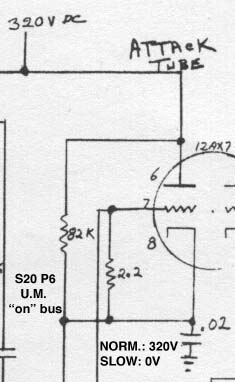
What happens on the FL when a key is released? First, let's say both STACCATO and SUSTAIN are off, meaning that the sustain capacitors are in circuit (unlike on the LS when SUSTAIN is off), and the "off" bus on the lower manual connects to 0V through a negligible resistance. When the upper manual spring contacts its separate off, the corresponding NE-2 bulb instantly fires and discharges the sustain capacitor quickly (through about 60kΩ resistance) down to just above the bulb's extinguishing voltage (which is roughly 50V). This keying control voltage is below the signal-passing threshold of the neon gates (which should be around 60V for LONG sustain), so even though the sustain capacitor then exibits a slow discharge to zero, it has no audible effect. Turning on SUSTAIN, the "off" bus voltage on the lower manual becomes 90V instead of zero. As before, neon firing and sustain capacitor discharge occurs upon key release as before, except that the sustain cap discharges quickly to the neon extinguishing voltage plus 90V, so let's say 140V. This is well above the signal-passing threshold of the neon gates, yet well below the 320V keying voltage exhibited while holding the key. What this means audibly is that the loudness quickly drops upon key release, then decays slowly from reduced level. In terms of its loudness envelope, the effect is reverb-like, yet lacks the richness of true reverb that results from acoustic signals travelling multiple distances and thus having widely varying delay times before being recombined. Lowrey nonetheless called the sustain feature in the FL owner's manual "reverberation of a most authentic nature"! While charging and discharging of the sustain capacitors with the SUSTAIN and STACCATO tabs off may be quick, it is not instantaneous, and so it lends a slightly sluggish attack and release to the notes. For really fast and percussive styles, this is best done away with; thus is the purpose of the STACCATO tab, which disconnects the sustain capacitors from ground, eliminating them from circuit. Not only is the resulting attack extremely fast, but it also exhibits a noticeable "thump" due to the DC offset imparted by the electronic keying system; see the LS article for more details on that. Release is not quite as fast (and hence does not exhibit thumping); undoubtedly there is some capacitance within the keying "packs", and about 60kΩ resistance that this capacitance must discharge through upon key release. In any case, the function of the STACCATO tab on the Festival is exactly the same as performed by the SUSTAIN tab on the Holiday series, Heritage series, and others. This is why the presence or lack of a STACCATO tab is a clear indicator of whether a given Lowrey tube organ uses "reverb-like" or "true" sustain respectively. Note that the presence of a manual coupler tab is not an indicator of this, since Lowrey also used a coupler system that gives "true" sustain (e.g. on the LSC and DSO); basically, they removed the "off" bus on the lower manual! As for sustain length, it is controlled by the DC bias voltage applied (through high impedances) to the 8'-4'-2' collectors: in this case +20V in medium sustain mode, or -30V in long sustain mode. This change in voltage primarily affects the proportion of the sustain capacitor's discharge curve over which then neon gating lamps pass signal. A few brief notes on the swell-to-great manual coupler. Firstly, it should be obvious how it works; when the coupler tab is turned on, it places high voltage on the lower manual's "on" bus, so that the neons fire and pull up the upper-manual springs (i.e. keying lines) to B+. Because there is 47kΩ in series with each bulb, the attack is rather slow—so slow, in fact, that the MANUAL ATTACK tab makes practically no difference in the coupler's expression. The LOUD/SOFT (or "FULL/SOFT") tab simply switches between full and reduced B+. Actually, my instrument is not wired quite like the schematic; an NE-2 bulb sits between the spring of the LOUD/SOFT tab and the "on" contact of the manual coupler tab (with 2.2MΩ from this contact to ground), and the upper and lower contacts of the LOUD/SOFT tab connect to 360V and 320V respectively. As a result, the "on" bus voltage measured about 300V on LOUD/FULL (somewhat lower than expected, probably due to an aged bulb), insufficient to give "full" keying voltage to the upper manual springs, considering the drop across the coupler neons and resistors. I may at some point try to modify this. It is so comparatively easy to modify tube-based equipment to achieve just the performance you want. One consequence of this coupler design is that sustain behavior can come moderately close to "true" simply by using the SOFT coupler and LONG sustain. This absolutely minimizes the difference between the "on" voltage (which is reduced to about 210V as compared to 320V) and the initial "release" voltage (about 150V, which does not change with the coupler settings). To finish off the keying description, I will explain the MANUAL ATTACK function, which is not present on the LS, and which is amazingly effective for how simple it is. There are two settings: NORMAL and SLOW. Only the sustain registers are affected, and the effect works by "softening" the B+ supply to the upper manual's "on" bus. Have a look at the circuit:
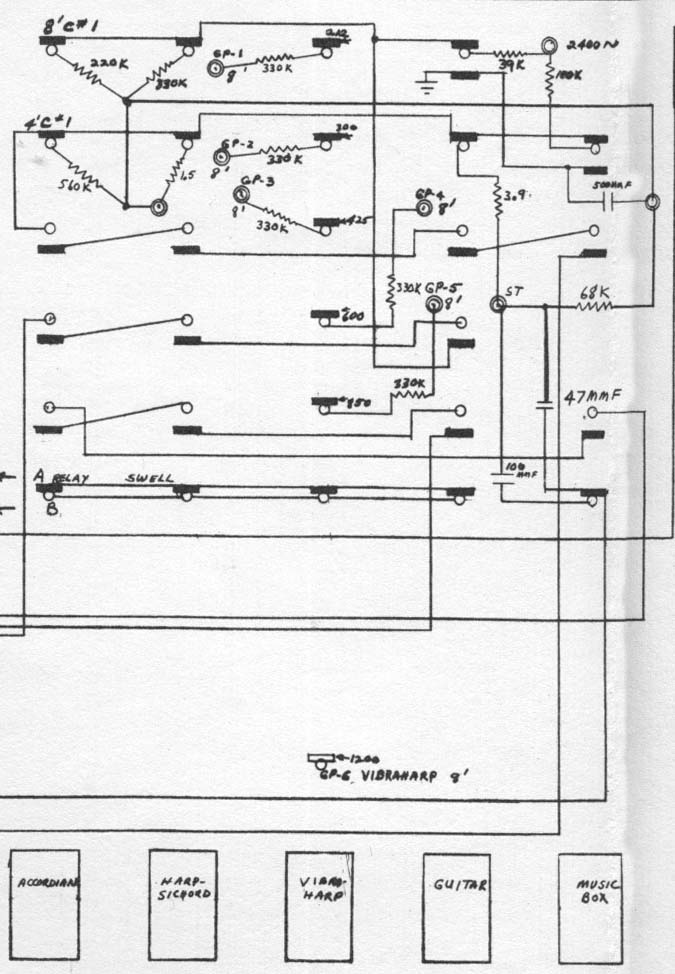
The cathode of the "attack tube" connects directly to the upper-manual "on" bus. In NORMAL mode, the tube's grid is held at 320V, meaning the tube will try to supply whatever current necessary to keep its cathode at 320V. This makes for a nice stiff supply to the "on" bus, nearly as good as if it were directly connected to the 320V rail. However, in "slow" mode, the tube's grid is grounded, cutting off the tube extremely hard (in fact, the 12AX7's rated maximum negative DC grid voltage, 50V relative to the cathode, is exceeded by about 540%!) Current must instead flow through the 82kΩ resistor from the 320V line to the "on" bus, resulting in sag as the sustain capacitors charge, giving nice slow attack. Since the entire keying B+ line is affected, you might think the attack recurs for every additional key pressed (thus "retriggering" all held notes); however, once at least one capacitor is charged up, the sagging effect of charging another is not nearly as severe (since some charge is borrowed), thus repetition of the attack effect is not really significant, thankfully! Tone shapingShaping of the tones is done mostly by various filter-amps, which are resonant lowpass types as usual. Routing of signals via the stop tab switches is rather complex, and often passive parts are used for emphasis before the filter-amps. This is all quite similar to the LS, except that in order to have entirely separate output channels for the two manuals, there are two separate sets of filter-amps. Both manuals have the same set of resonant frequencies, which are 212, 300, 425, 600, 850, 1200, 1700, and 2400 cps. Each manual also has its own non-filtering "string" amp, and a "pre-amp" stage that amplifies the combined output of all filters. The swell manual also has a "doubler amp", taking signal from the 3400 and 4800 cps doubler coils, while the great manual simply feeds its 3400 cps doubler coil to its "string" amplifier. Now for some fun. Among the few who know of Lowrey's tube organs, many do only because of Lucy In the Sky With Diamonds, on which a "Heritage" model DSO was played distinctively. In his book Beatles Gear, Andy Babiuk stated that McCartney only used the preset tabs: Harpsichord, Vibra-Harp, Guitar, and Music Box. My FL has the same selection of tabs, yet no matter what I tried, I couldn't get nearly the same bright shimmering tone heard in the intro. Some have said that the intro makes use of the Harpsichord preset alone, and I don't doubt it, yet on the FL, this preset sounds nothing like a harpsichord; it is much too "hollow" and dull. Another Lowrey owner, with whom I discussed this question on the Organ Forum, had the same complaint about his "Lincolnwood" model SS (introduced 1957). For one, we know that the DSO has true sustain, while the FL and SS have reverb-like sustain, meaning the expression of the notes will never be quite right (though as I mentioned earlier, it can be made decently close using the swell-to-great coupler in SOFT mode with LONG sustain). We also know the FL (but probably not the SS) has flawed vibrato to begin with, which I fixed through modification. But the main problem is the difference in timbre. So, I decided to really compare the Harpsichord tab circuitry on the FL and DSO schematics. To spoil the ending, it turns out there is a difference significant enough to make the sound properly "full" and "harmonic-heavy" on the DSO even though it isn't on these earlier models! On the FL, the Harpsichord tab adds "8' Collector #1" and "4' Collector #1" together through 330kΩ and 1.5MΩ respectively, then rolls off high frequencies with a 500pF capacitor to ground, then routes the signal to the non-resonant String amplifier. This can be seen below; note that all tabs are shown in "on" position.
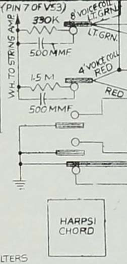
A few things to note. Firstly, those collectors are formed by adding together all the individual collector "groups" of 8' and 4' pitch respectively, the signals on which are squarewaves. If we assume the 8' and 4' collectors have roughly the same signal levels, clearly much less 4' is added than what you'd expect from normal "staircasing" (i.e. 1/2 of the 8' amplitude), hence explaining why the resulting sound is too "hollow". In fact, I would think that ideally more 4' should be added than the usual for staircasing, in order to imitate the classic double-rank harpsichord sound. Secondly, the combining resistors and 500pF capacitor form a lowpass filter with cutoff frequency of about 1100 cps; this explains the lack of brightness, eh! A harpsichord is supposed to be among the very brightest string instruments, yet they are severely dulling the sound? What were they thinking!? Well, it took a few years, but eventually Lowrey's designers noticed and fixed their mistake. On the DSO schematic, they call the combined collectors "voice collectors", and the way the groups are combined is practically the same as on the FL. On the Harpsichord tab, the 8' and 4' voice collectors are added through 330kΩ and 1.5MΩ respectively, as before. However, rather than having 500pF to ground afterwards, there is no such capacitor, and both of the summing resistors have 500pF in parallel! This means the high frequencies are emphasized instead of reduced, and I mean significantly — consider that the reactance of a 500pF capacitor is only about 160kΩ at 2000 cps, completely overwhelming the 1.5MΩ resistor especially, and thus adding much more 4' than the FL's circuit does.
So, the DSO's Harpsichord tab must sound much brighter, and could very well be described as "harmonic-heavy" and "full"! It might even be the Lucy sound, though we'd need someone to make a good demo recording (probably with LIGHT and FAST vibrato and LONG sustain) to be sure. With this, I will conclude the Electronic Design section; the rest of the FL's circuitry is either trivially different from the LS, or has to do with amplification and power supply, which is all standard and easy to figure out, at least in comparison with the many bizarre and complex circuits we have just looked at. The SoundsBelow is a short video demo of the FL, the first portion of which demonstrates each function individually, after which there are musical demos. It was made before I found a pedalboard. Some time soon, I will use the FL in "real" recordings, which may be placed here. Gallery
|
| If you notice any errors or have additional information that you would like to add, please contact me! |


First Published: 07/25/2020