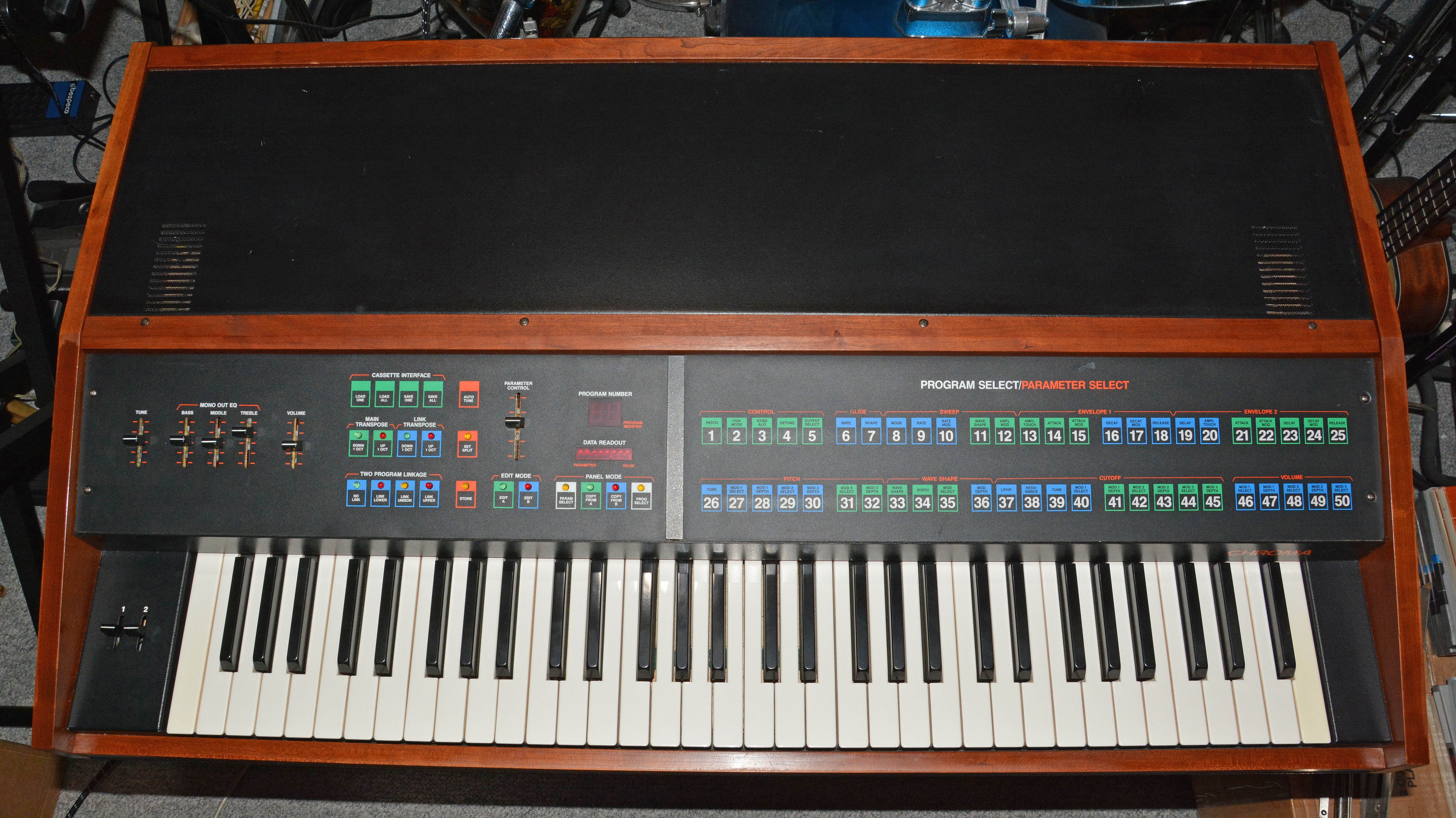
Rhodes Chroma 2103Polyphonic Digitally-Controlled Analog Synthesizer
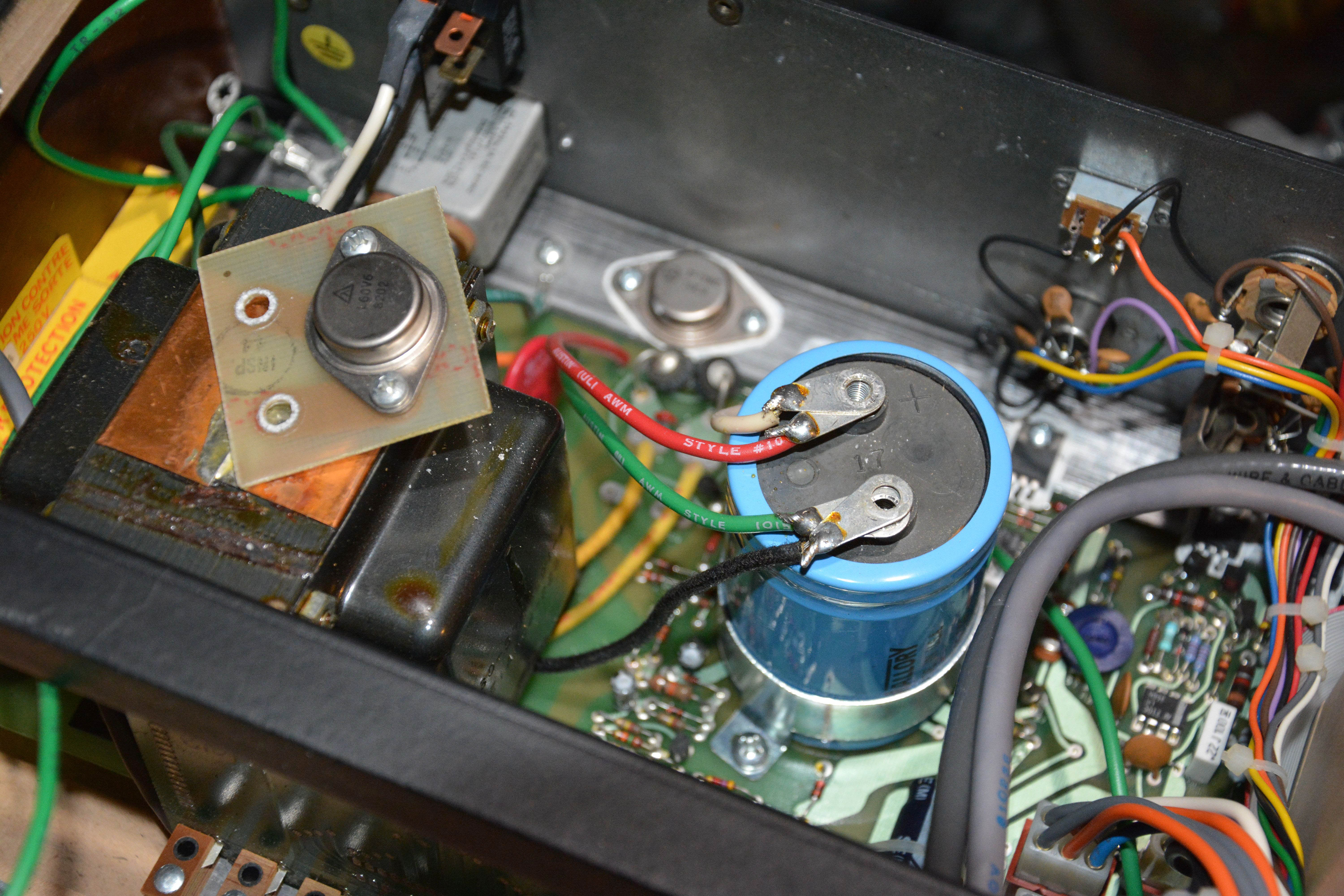
This article will describe my experience repairing a Rhodes Chroma 2103 in mid-2018. I don't intend to deeply explain the instrument's functionality or history, since this info is readily available online, especially from the dedicated Rhodes Chroma Website. Rather, I hope that my experience will be valuable to someone encountering similar problems repairing a Chroma, or that at the very least, it will make for interesting reading. Suffice it to say that the Chroma is among the most capable and great-sounding polyphonic analog synths ever made. The repair of this Chroma was entrusted to me by a music professor at the University of Alberta. He purchased it from a friend (the first owner) for $2,500 in around 1985, along with an Apple II and its interface (now missing). At some point in the 90s, the Chroma was put in its case for transport, and when tried again decades later, it was no longer working. RepairsThe instrument was functionally dead to start with. The tapper solenoid (which is used to add tactile feedback to the membrane switches) repeatedly tapped, and none of the membrane switches did anything. Whenever an electronic device is in such a dysfunctional state, the first thing to check is always the the power supply circuitry. Sure enough, the "digital 5V" rail measured about 2V—all other rails checked normal. Looking on an oscilloscope, there was ripple on the rail in question, so I immediately suspected the associated filter capacitor (C3 in the schematic), which is 47,000µF at 7.5V, Mallory type CGR. Sure enough, it measured 4.5Ω on the ESR meter, when a good reading for this capacitance is about 0.01Ω or lower!
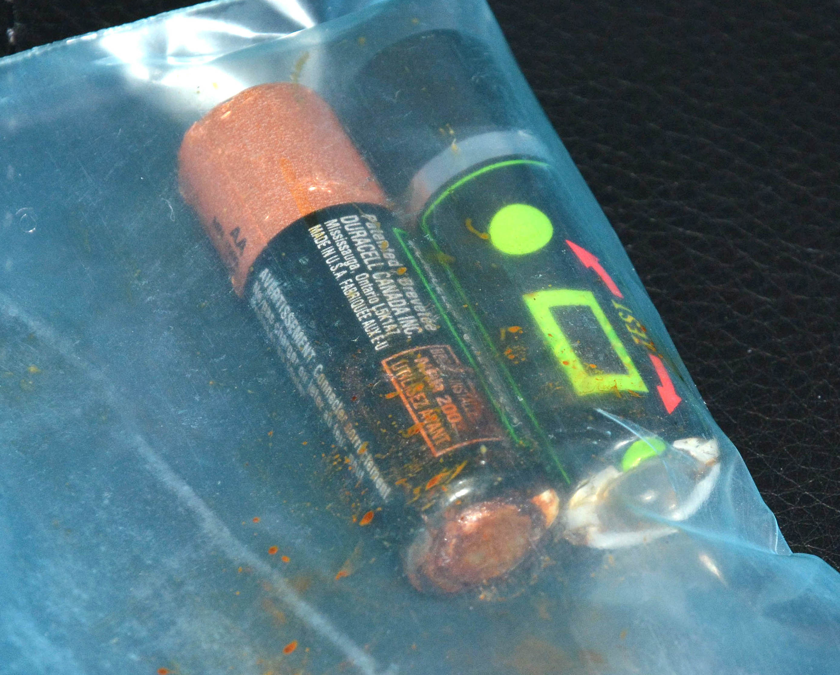
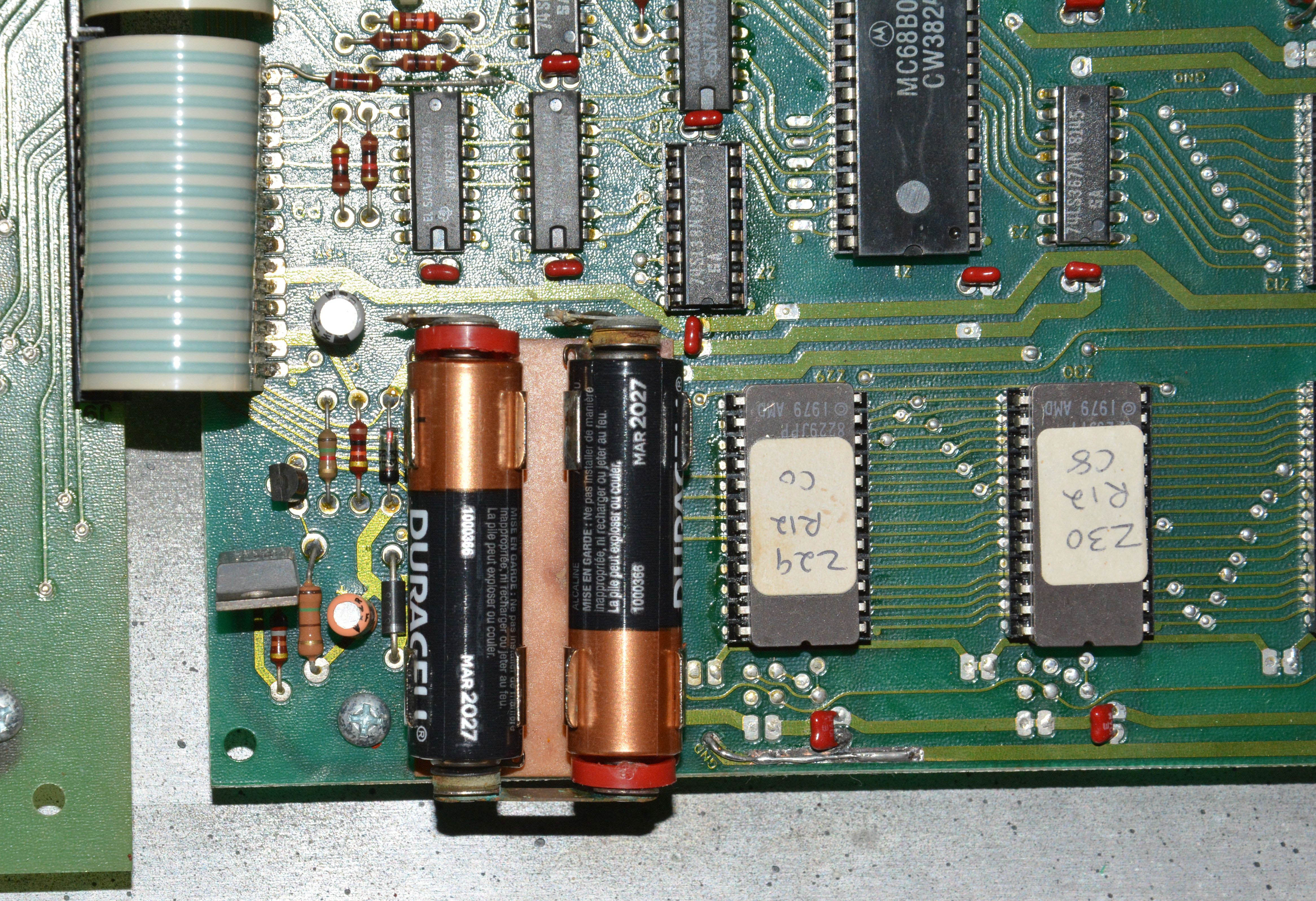
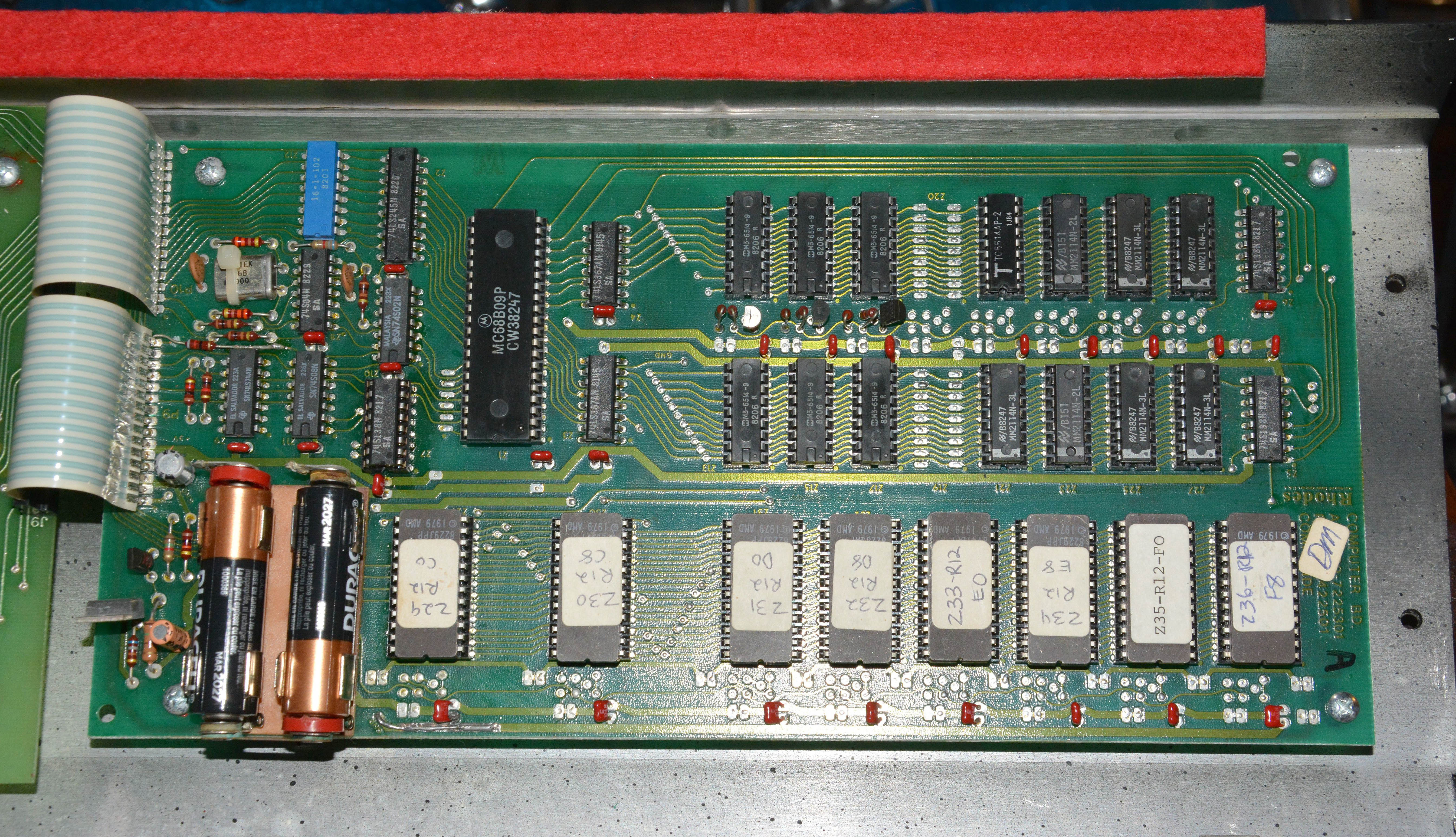
I replaced this capacitor with Digi-Key part 495-4223-ND (47000µF 40V), which is physically a perfect fit, and with a relatively long rated life: 12000hrs @ 85ºC. It also has a working voltage over 5 times higher than the original part, which should not be a problem, though it makes me wonder what has been "compromised" to allow higher working voltage in the same can size. I also replaced the bolt holding C3 in its clamp, since it was severely bent. Then, I adjusted the digital 5V rail's output for 5.05V via R22, as measured at the PSU board's connector under normal load, as recommended in Martin Straw's Hardware Fault Diagnosis & Repair guide on rhodeschroma.com. Checking the power supply voltages, they were now all correct and clean. Just another typical electrolytic capacitor job, right? However, the Chroma was still not working; when powered, it would start by flashing of all LEDs together 16 times (indicating normal testing of the 16 voices). It would then usually "freeze" immediately, with the display/LED multiplexing slowing to a halt (or immediately halted), and with no response to keys or buttons, and no sound at the outputs. Now, before I tell you what the problems were, I should mention briefly that the Chroma's power supply section is notoriously unreliable, and is the main focus of the troubleshooting article linked above; after all, 7 of the 8 most common faults have the power supply listed as the likely cause! However, in this case, I knew the power supply was not to blame, simply because I measured it, and it was good, including at the computer board where the digital 5V rail is most important. No, the remaining problems had nothing to do with the power supply. To begin with, the batteries used to retain the patch & other data in the CMOS RAM had leaked. This is a classic problem introduced in 80s and 90s gear especially (see the Peavey DPM3 SE for another commonly affected unit, with even worse placement of the soldered-in battery). I removed the two severely leaked AA cells from the computer board (shown below on the left), and cleaned the battery holder and surrounding area thoroughly with vinegar, followed by isopropyl alcohol and Electrosolve. They were replaced with new AAs with expiry in March 2027; I will have to remember to check them then, if not earlier! I also bridged a corroded ground trace on the computer board with a wire, and removed the board to check underneath for damage, of which there was none. The cleaned board with new AAs is shown to the right:
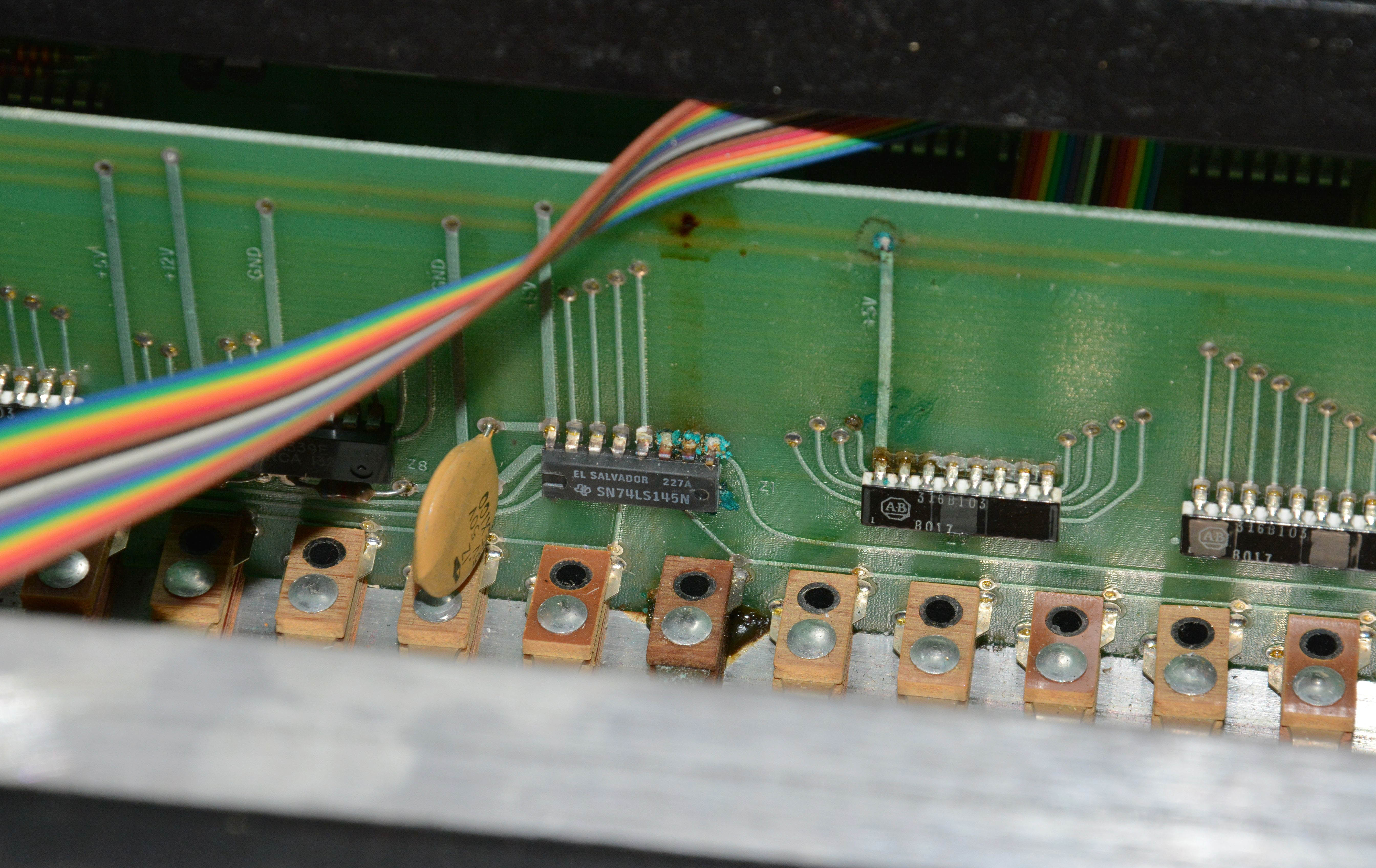
Before continuing with the battery cleanup, I should point out the white ribbon cables in the upper left. Be very careful with these, since they are probably the most fragile and low-quality parts in the whole unit. Not only are the cables known to delaminate if handled a little too roughly, but the connectors are also unreliable. In fact, in troubleshooting the computer board, I measured continuity between both sides of the ribbon cables, and found a few pins that were flaky (especially pin P9-13). I applied Electrosolve contact cleaner to the female connectors, and also slightly bent those male pins with poor contact towards their female mates. This restored good connection, at least for the time being. Now, back to the battery cleanup... Unfortunately, since this Chroma was stored in its case with its back towards the ground for over a decade, the battery leakage also seeped onto the right "stack switch" board, causing corrosion around Z1 (74LS145) and saturating the #56 (2nd highest E) keyswitch. Clear liquid drops also formed along the board edge, away from any traces.
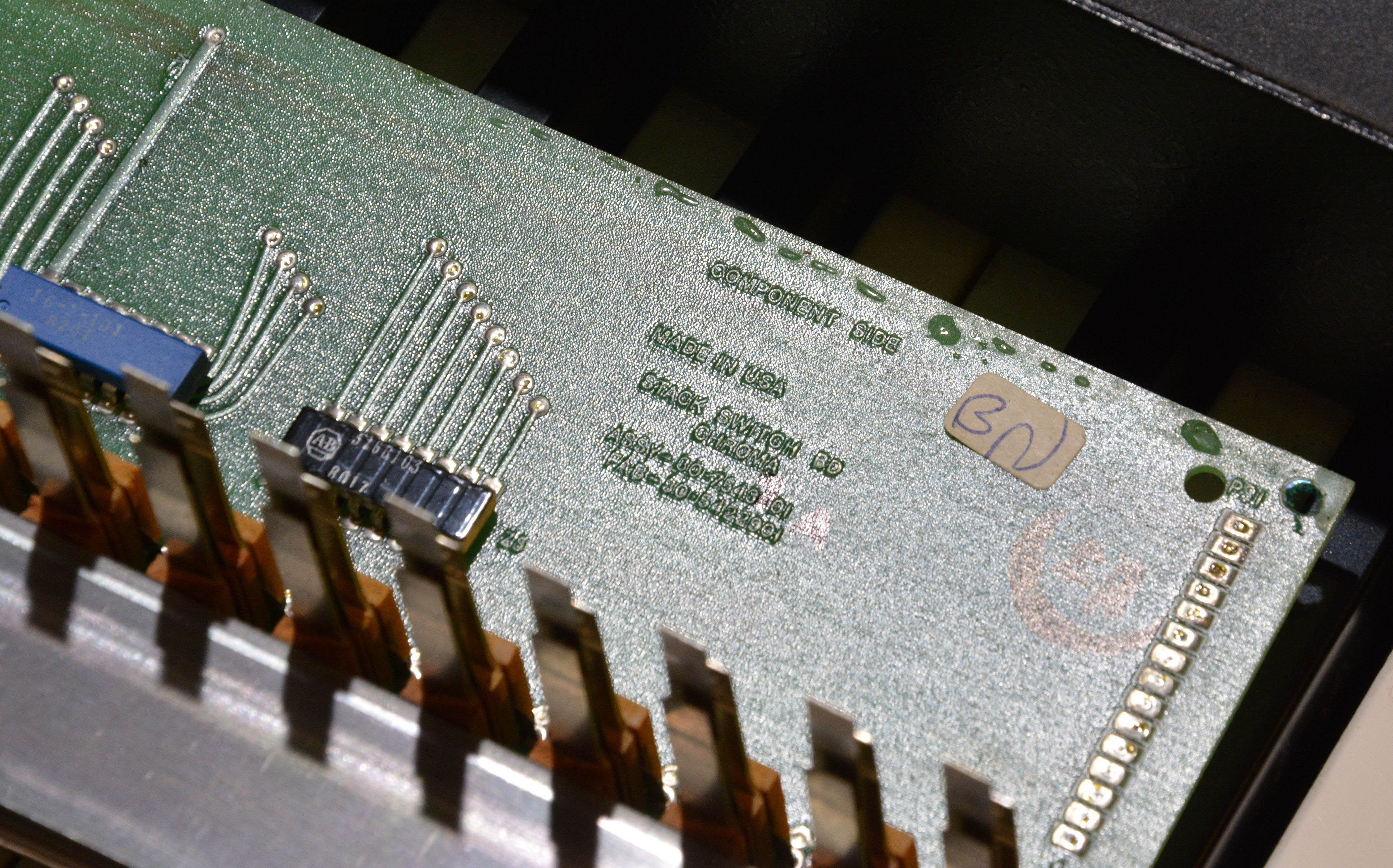
I thoroughly cleaned the battery juice off of this board, removing Z1 and installing a socket. Z1 was found to be functional and in good condition after cleaning. Three jumper wires were added to bridge corroded-through connections. Here's what it looked like at this point:
With the board reinstalled, the instrument now did not freeze instantly on power-up; it properly indicated on the display and discrete LEDs, and responded correctly to all membrane switches. I was thus able to load into memory a set of factory patches (available here) by means of the cassette port: a 5-pin DIN connector with input signal applied to pin 5, and pin 2 grounded, as shown here. I connected my computer's output jack to the port with a basic clip-lead setup, and followed the procedure here. After a few tries to get the output level right, I settled on close to maximum output from my A1278 MacBook Pro, and the patches seemed to load in without errors. Despite this, most patches did not sound anything like their names ("strings", "harpsichord", "gong", etc.), and the instrument still froze when either playing the #56 key (which would simultaneously sound many adjacent notes), or when holding 5 or more keys at once. Suspecting the #56 keyswitch of still being saturated with conductive battery juice, I checked the resistance across it, and it was in the single-digit kilo-ohms! So, I pulled out the board again. I then desoldered the switch and drilled out the rivet, allowing the switch to be removed. Without the rivet, the switch is held together only by friction between the phenolic wafers and the two hollow plastic cylinders. With careful prying, the sections can be separated and individually cleaned, which I did using vinegar followed by isopropyl alcohol. Reassembling the switch, it still measured about 1MΩ across the outer contacts, so in frustration, I threw it into a jar of isopropyl alcohol and let it sit overnight. In the morning, I removed the switch, dried it with paper towel, then "baked" it for about 30 minutes in my Nesco FD-60 food dehydrator at 135ºF to evaporate the remaining alcohol. Finally, the switch measured "O.L." between all contacts on my multimeter. Then I reinstalled it with a 4-40 bolt, lock-washer, and nut, with a small drop of cyanoacrylate glue to prevent gradual loosening.
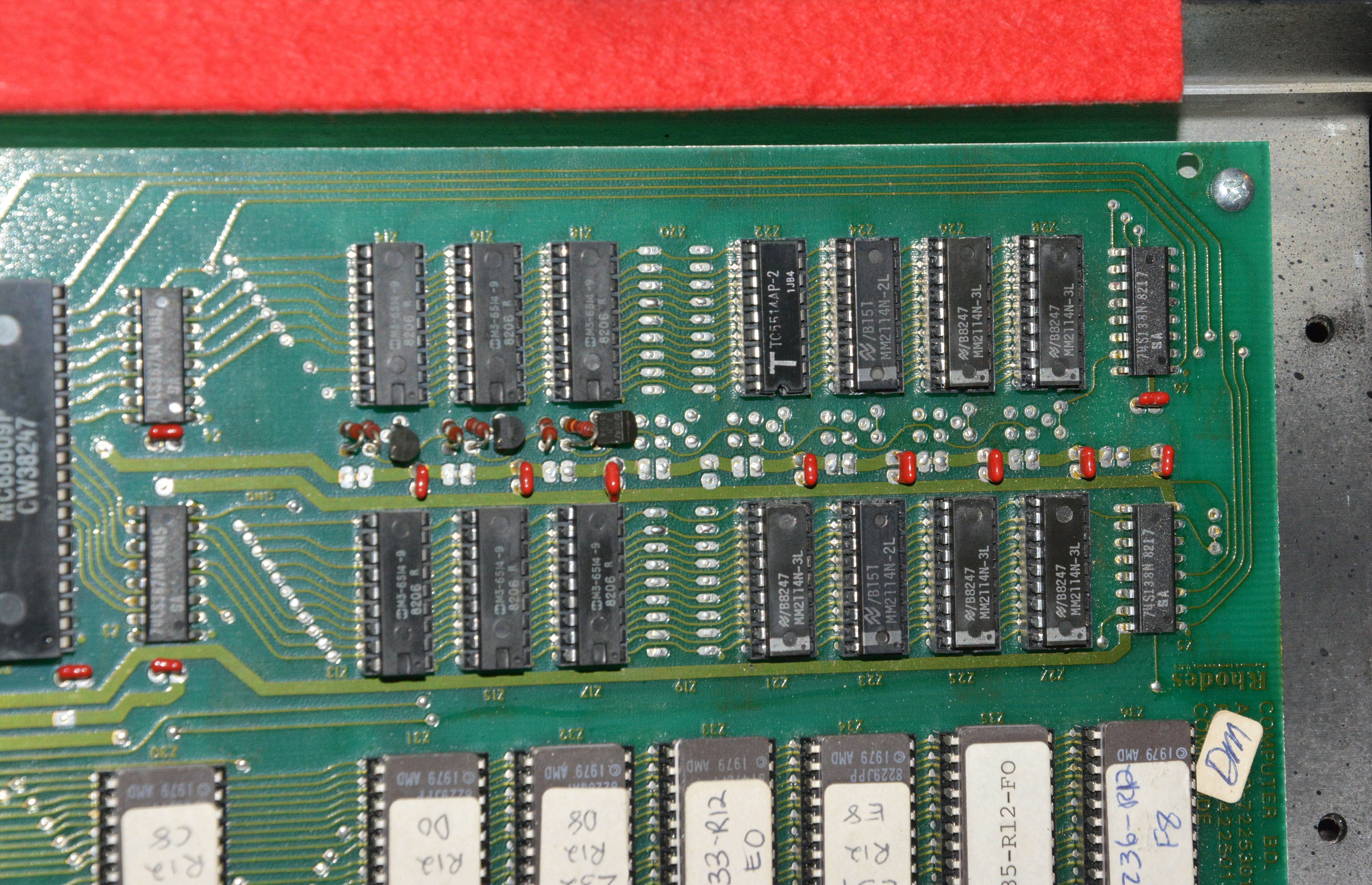
With the switch reinstalled, the #56 key now played properly, resulting in no adjacent notes sounding, nor instant freezing. However, playing 5 or more notes at once still resulted in freezing. Eventually, my suspicion turned to the memory chips, because if one was bad, it would explain the strange-sounding patches (due to corrpution of the data) as well as the crashing, if some damaged part of the memory was used for the 5th note processing. The Chroma contains two banks of SRAM memory on the "computer board": CMOS and NMOS. Both types of chips are basically the same besides the technology, containing 1024 4-bit words each. The CMOS SRAM consists of six 6514-9 (for a total of 3KB), and is used to store the patch data, since it is made non-volatile by the batteries. The NMOS SRAM consists of eight 2114N-2 (for a total of 4KB), and is used for data structuring / scratch-pad operations. Since I already had some Toshiba TC5514AP-2 CMOS chips (which can substitute either the CMOS or NMOS), I just started swapping them, starting with the NMOS bank, going counterclockwise from the lower left. Of course, between each chip replacement, the unit was powered off. No effect was noted until I replaced the upper left NMOS chip (the very last one), at which point the instrument did not freeze anymore! After re-loading the patches, they finally sounded like their names. I sincerely thank ARP/Rhodes for putting the SRAM chips in sockets; if they hadn't, this would've taken at least 5 times as long, and I would've been much less inclined to do it in the first place. Here's the board after repair, with the replaced chip showing a big T for Toshiba:
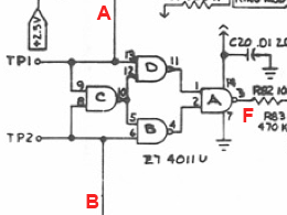
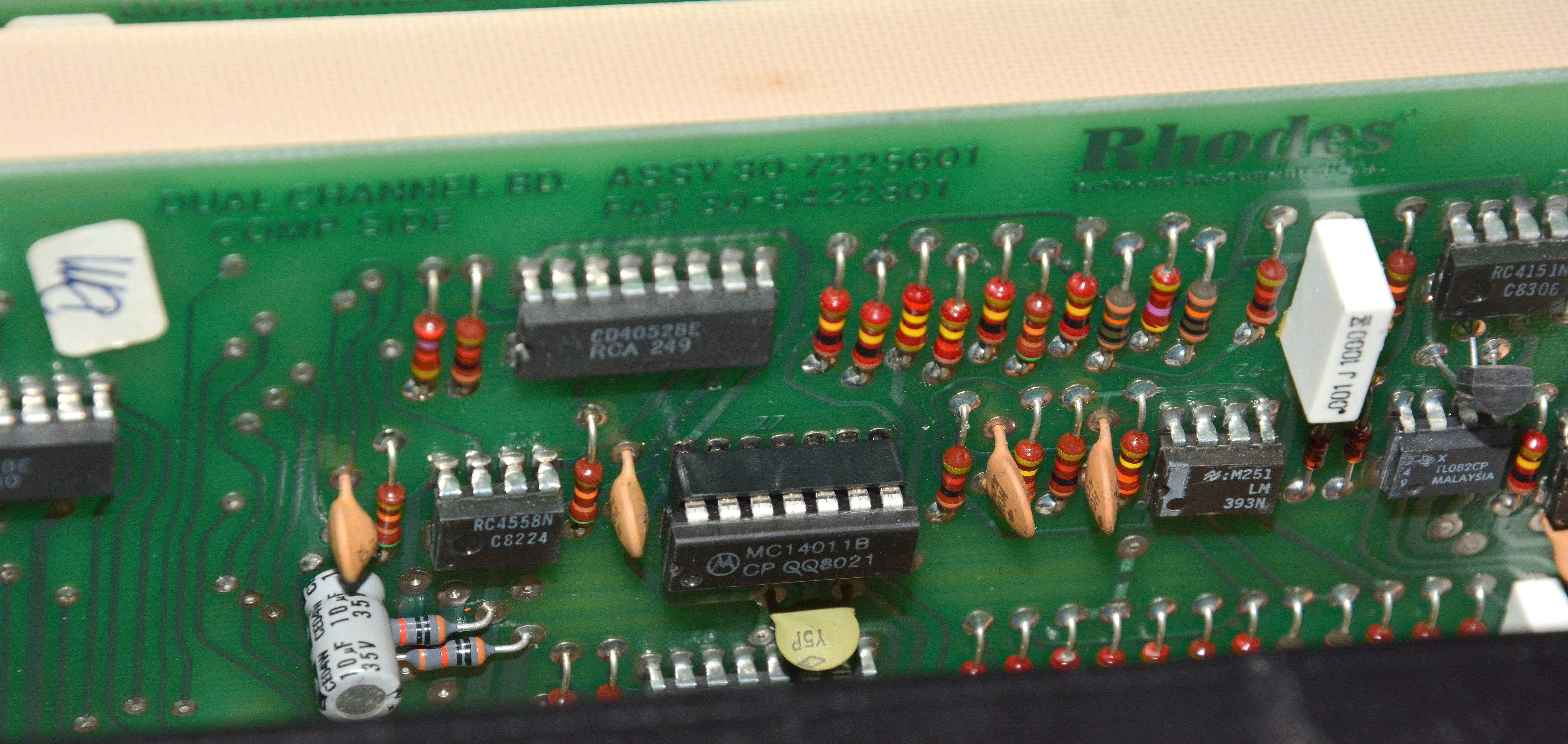
The final electronic repair came when I noticed that the ring modulation was not working on one voice. On the Chroma, each "dual-channel" board has a ring modulator section comprised of a single 4011 logic chip, containing four 2-input NAND gates. You may wonder: how can such a simple digital logic chip implement ring modulation? First, keep in mind that ring modulation is simply multiplication of two signals in the time domain. This can be represented mathematically as the function f=a·b, where a is the first signal, and b is the second. Normally, these signals vary continuously in amplitude. However, in the Chroma, the inputs to the ring modulator are always the pulse-wave outputs of the two oscillators, which are inherently "digital" to begin with, since pulse-waves have two discrete voltage states. This explains how the oscillator's signals are compatible with digital circuitry, but then how is the multiplication actually implemented? To explain that, we have to move into the domain of Boolean algebra. Below is the actual circuit from the service manual, with labels added to indicate the inputs A and B, and the output F.
Looking at this, it can be seen that it implements the boolean function F=((A(AB)')'(B(AB)')')' where AND, OR, and NOT operations are represented by multiplication, addition, and "priming" respectively. By the laws of Boolean algebra, this function can be simplified to F=AB'+A'B, meaning that the entire circuit is equivalent to one 2-input XOR gate. Below left shows a standard truth table for an XOR gate, labeling the lower-voltage state "0" and the higher-voltage state "1" as usual. However, this isn't the ideal notation, because the numbers don't compute as expected; 0 times 0 is definitely 0, but 0 times 1 isn't 1, nor is 1 times 1 equal to 0! To understand why the XOR gate gives a perfect ring modulation, we have to rewrite "0" as "-1", to reflect that the input signals have 0 average amplitude (i.e. no DC offset), and also to give the same output amplitudes as input. The revised truth table is shown to the right; now it's clear that it's a perfect ring modulator, except that the output is inverted (which has no effect on the sound).
Coming back to the repair, sure enough, one of the 4011 chips was bad on one of the dual-channel boards, with the output of gate "A" never changing state. I don't remember exactly how I found which one was bad — I might have checked test points 1 and 2 while pressing different keys until I saw the frequency change and heard the defective ring modulation. Anyway, despite Rhodes using a double-sided board, desoldering was not too difficult (using a normal iron with fluxed solder wick) thanks to large pads, thick copper, and good adhesive — no pads were lifted or otherwise damaged. I installed a socket in place of the bad chip, in which I put the Motorola equivalent, an MC14011B.
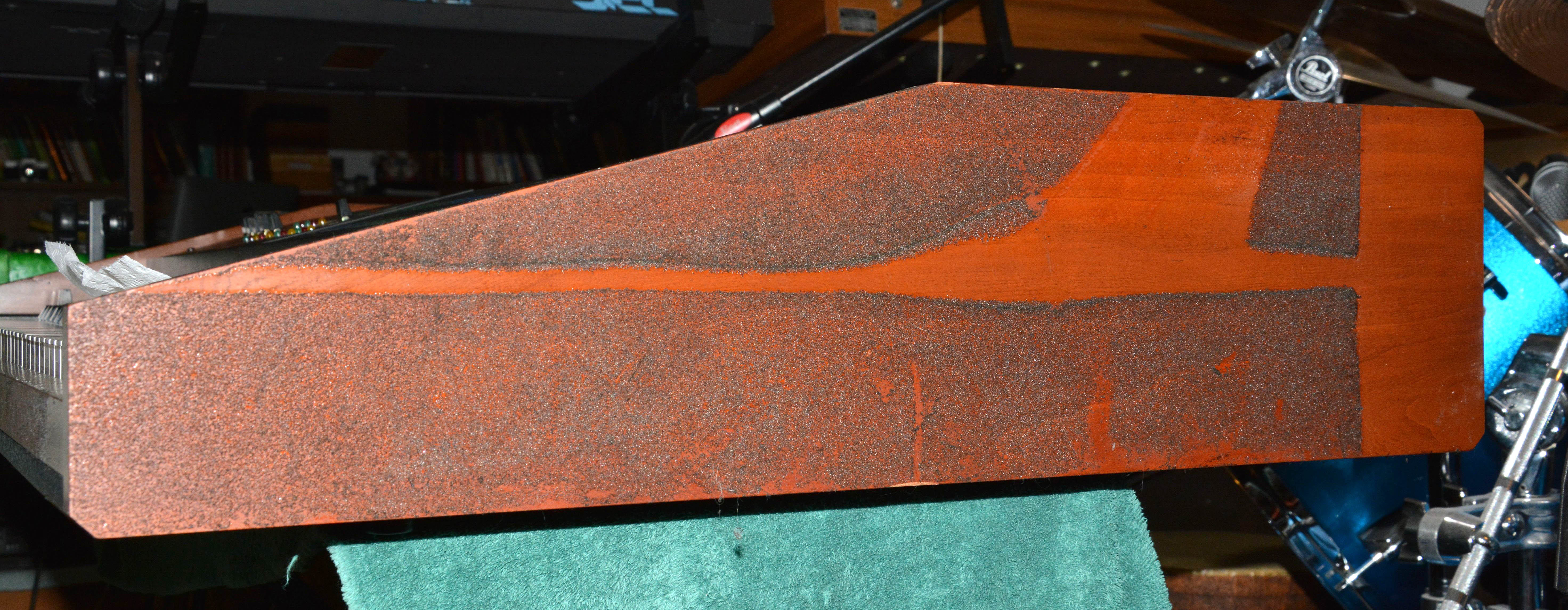
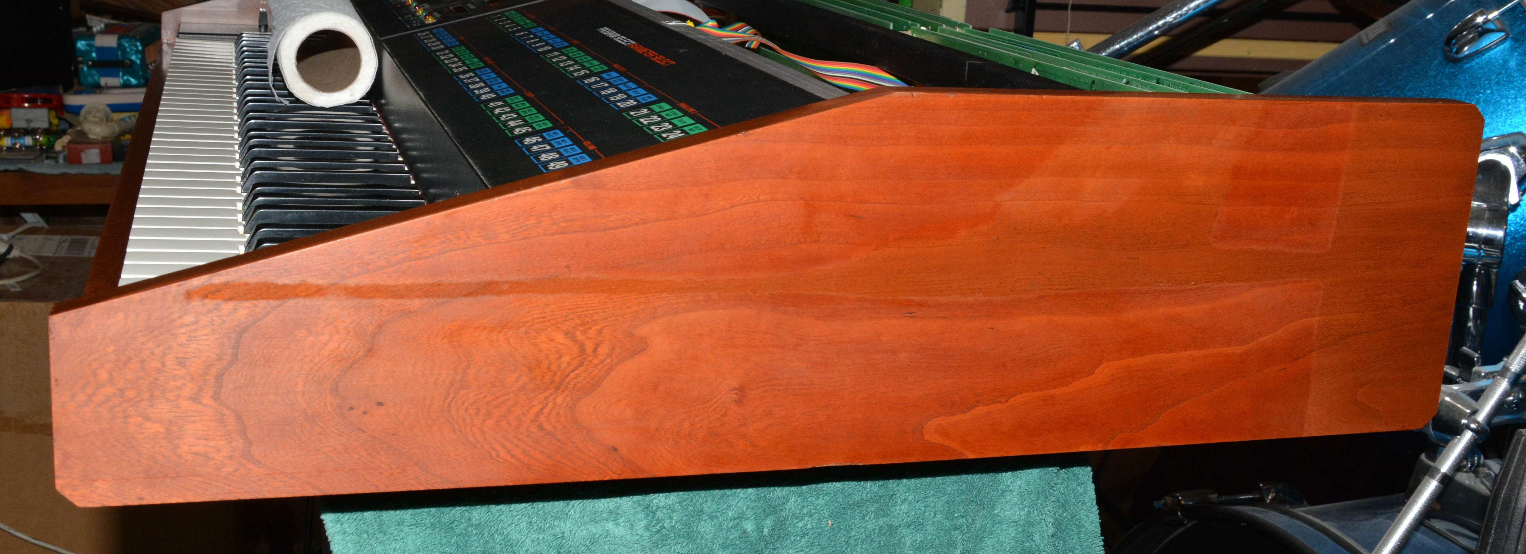
Upon reinstalling the board, I took the opportunity to clean the pins of all of the channel board connectors with isopropyl alcohol, and Electrosolve (once boards reinstalled). This solved the issue of some boards occasionally failing during auto-tuning. That concludes the electronic repairs; at this point, everything was sounding great. However, cosmetically, there were still problems. The Anvil case that Chromas came with uses a padding foam that by now has always decomposed. In my case, the foam had been all removed at some point, but not before reacting with the varnish on the wooden panels, turning it gooey and thus causing adherence of a layer of foam. I cleaned this up in a rather inefficient way: first using the edge of an old bank card to gently scrape as much of the foam off as possible, and then using isopropyl alcohol on rags to dissolve both the remaining foam along with the gooey varnish, which happened very slowly. Interestingly, the non-gooey varnish (that hadn't touched foam) was not dissolved in alcohol. I probably should've just removed the panels and used lacquer thinner, thus taking off both the rotten foam and all of the varnish, and then recoated, since the wood is still in great shape. One day I will likely do that, but for now, the improvement is satisfactory:
So, to review, here are all the tasks performed to bring this remarkable synthesizer back to life (including some minor things not discussed above):
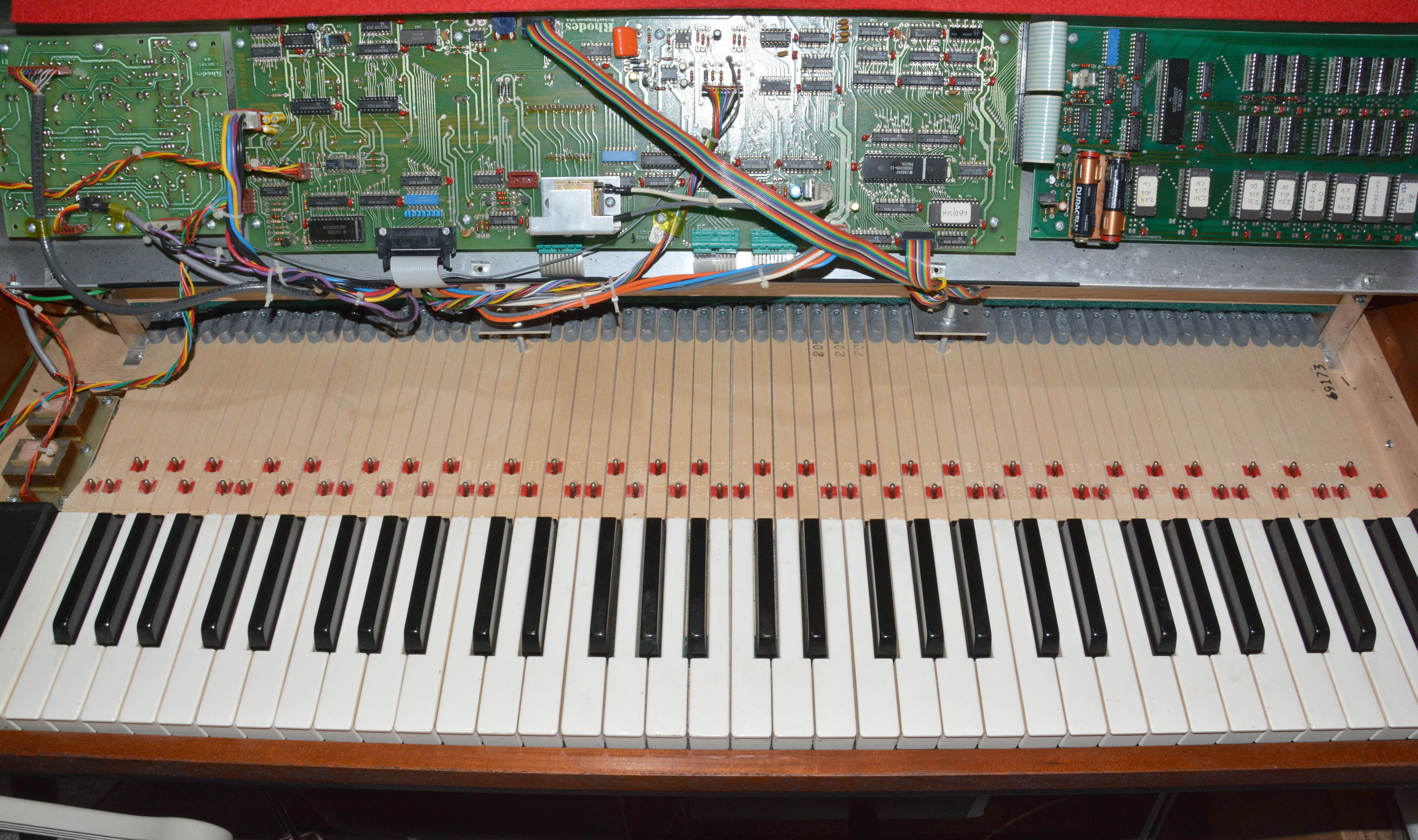
HardwareIn this section, I'll show some pictures of the insides, in order to show the design and materials quality of the instrument, and to assist anyone in need of reference shots of where things go, etc. To start, here's a somewhat cropped shot of the inside with the top panel hinged upwards, revealing the keyboard, EQ board (left), I/O board (middle), and computer board (right). Notice that the keys are remarkably high-quality: wooden, with felt bushings on metal pins, like acoustic piano keys. As we know, acoustic pianos with similarly made keys can last well over 100 years and remain playable, and they can be rebuilt at low material expense. The key levers are weighted at the ends (with what are probably lead slugs), giving a feel somewhere between an organ and acoustic piano. They are light enough to comfortably play, even with organ-style patches. As far as I know, there are no currently-made electronic keyboards that use such high-quality keys, even "professional" models.
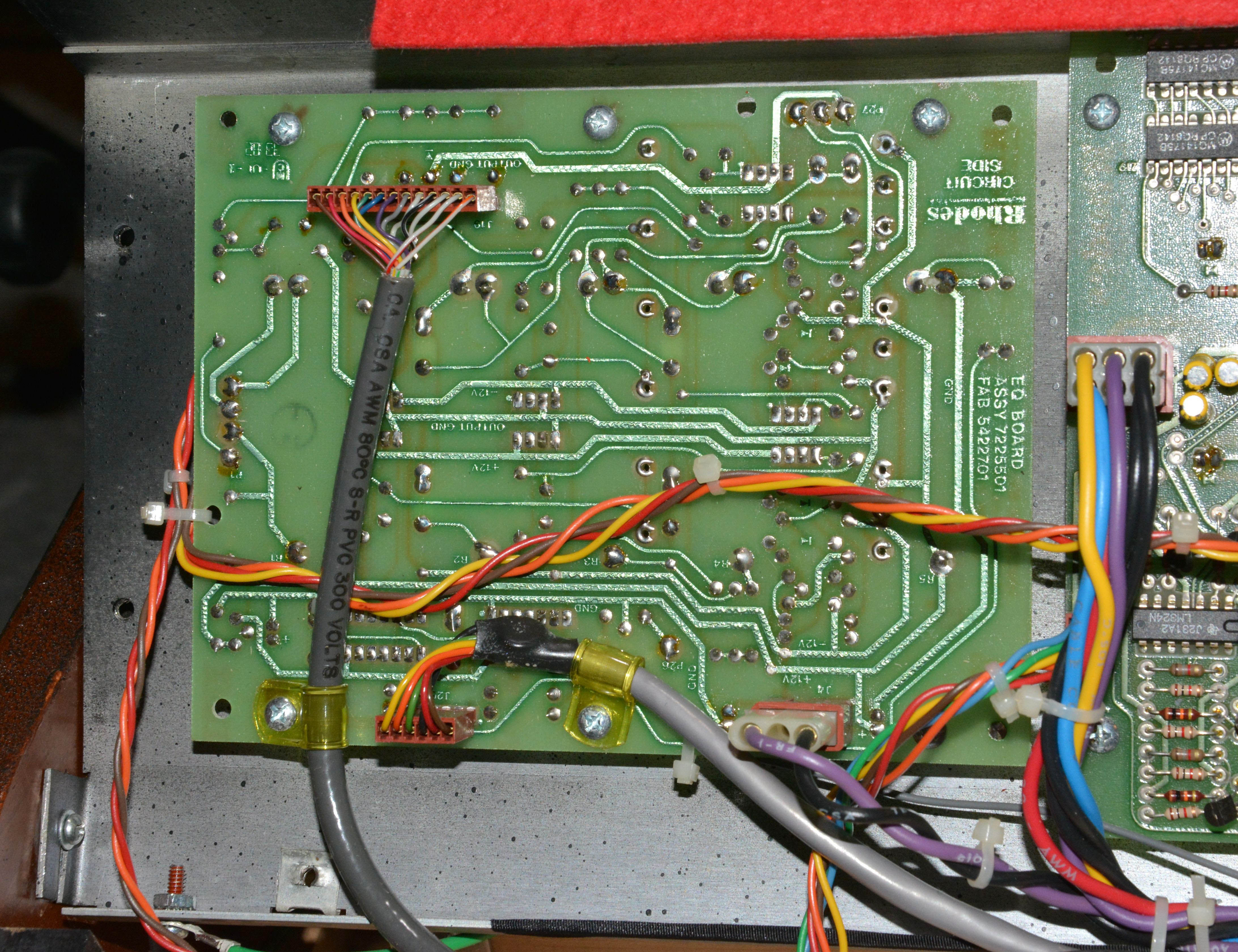
Below shows close-ups of the three boards mounted to the top panel, from left to right: the EQ board, I/O board, and computer board. Note that even on the relatively complex and dense computer board, there are curved traces most likely indicative of hand-routing. The 1980s was the transitional decade from manual drafting to CAD software, so these boards are relatively late and complex examples of hand-routing. Note that although not all chips are socketed, many are, including all of the large ones. Note that the pads are relatively large, and the copper is thick, making the boards relatively easy to remove parts from without damage, despite being double-sided.
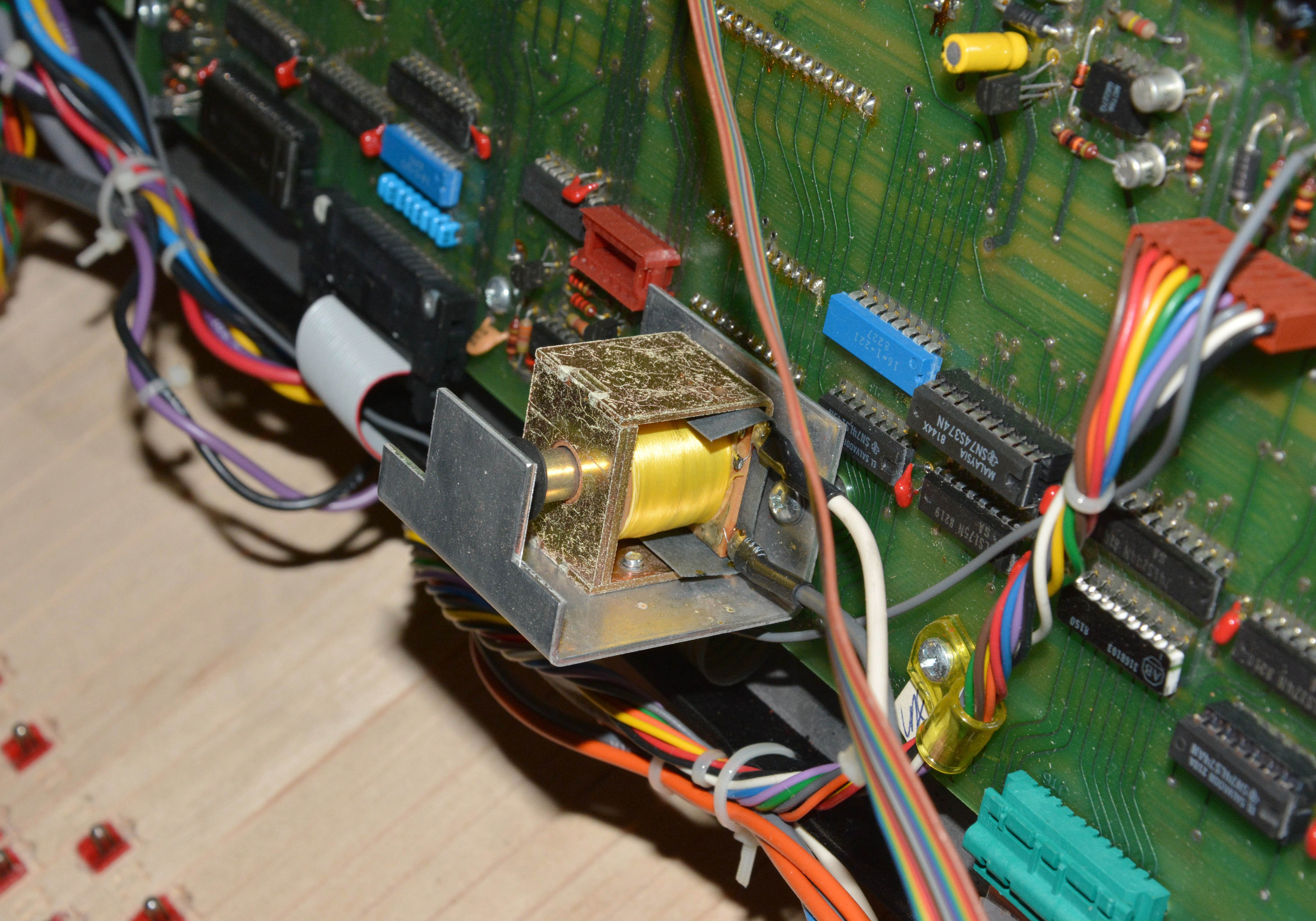
Below is the tapper solenoid, which adds some tactile feedback to the otherwise not-so-satisfying membrane switches, as well as the parameter slider.
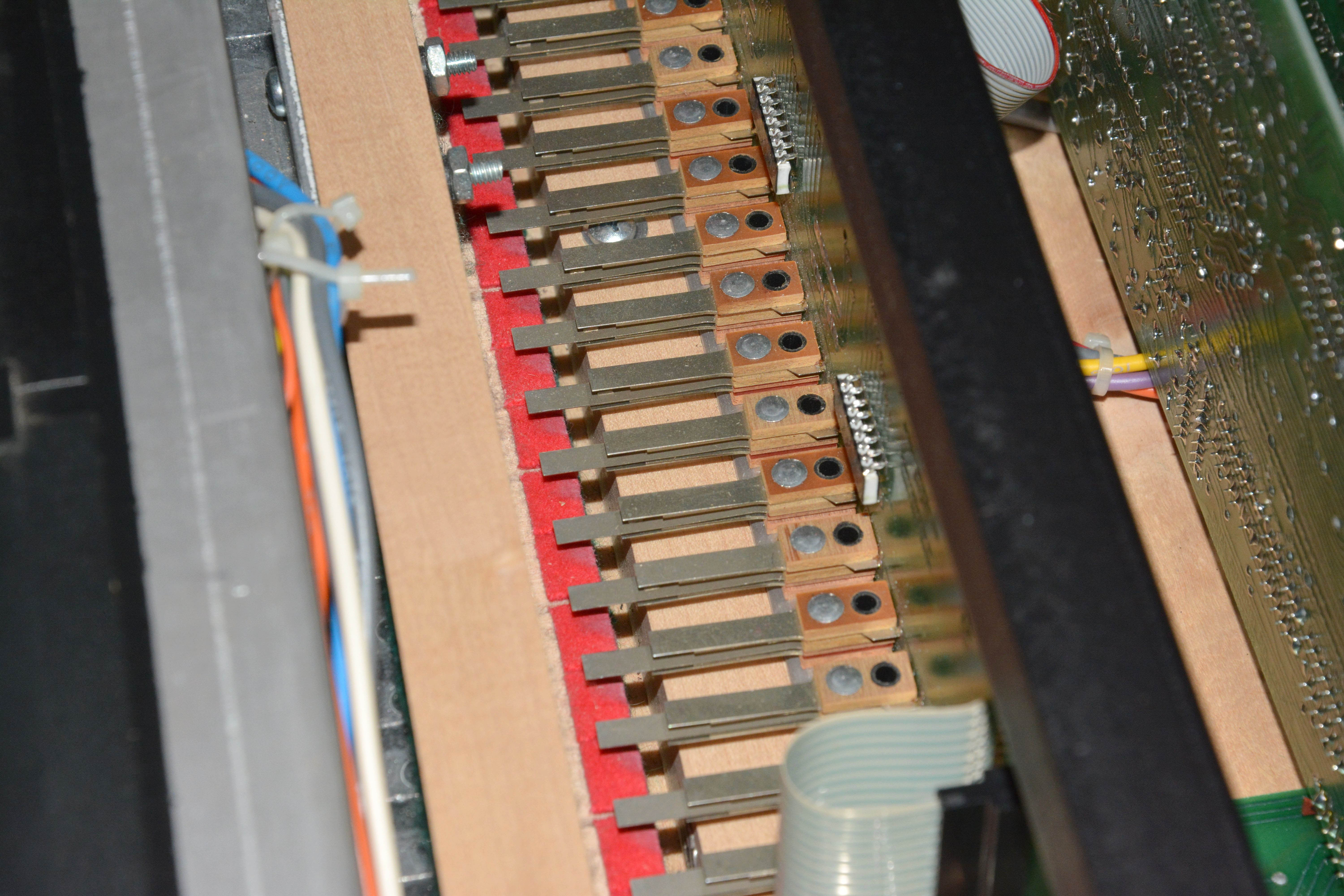
Looking behind the top panel, there are the keyswitches, dual-channel boards, channel mother board, power supply, and back panel. I just love the keyswitches especially, since they are both robust and serviceable. Although from this angle the contacts look like plain spring steel, there are actually crossed inlays of better contact material within the spring steel pieces. As explained in the repair section, the keyswitches can be removed individually from the board and completely disassembled. This is a great contrast to modern silicone-dome keyswitches, where the contacts are all printed on a long proprietary PCB, and which also use proprietary strips of silicone domes, the longevity of which is questionable. Nobody makes a set of keyswitches of this quality anymore to my knowledge, though I'd love to be proven wrong.
The power supply is shown below. Note the large 7.3V Zener diode in a TO-3 package mounted to the 47,000µF filter capacitor C3. This is part of the digital rectifier & pre-regulator circuit as shown here, and described here. Although the description explains this diode only as part of the pre-regulator's reduction of the power dissipation in the +5V digital regulator (by reducing the voltage into it), both I and another synth repariman called Synthchaser suspect that its main purpose is actually to prevent overvoltage to the original "wimpy" 7.5V capacitor C3. In Synthchaser's Chroma, this capacitor was high-ESR like mine, but also, the Zener diode had shorted. He decided to completely remove it (and readjusted the output voltage via R22), and noted no issues. See his Chroma repair video series here. Even though I replaced the capacitor with a much higher voltage one, I still reinstalled the diode as a nod to the original design, and since it indeed slightly reduces the +5V regulator's power dissipation, though I haven't determined by what proportion. It may be worth figuring out at some point though, since as it is, the Zener diode is nothing but a power-waster, and may put now-unnecessary strain on the pre-regulator transistors and power transformer.
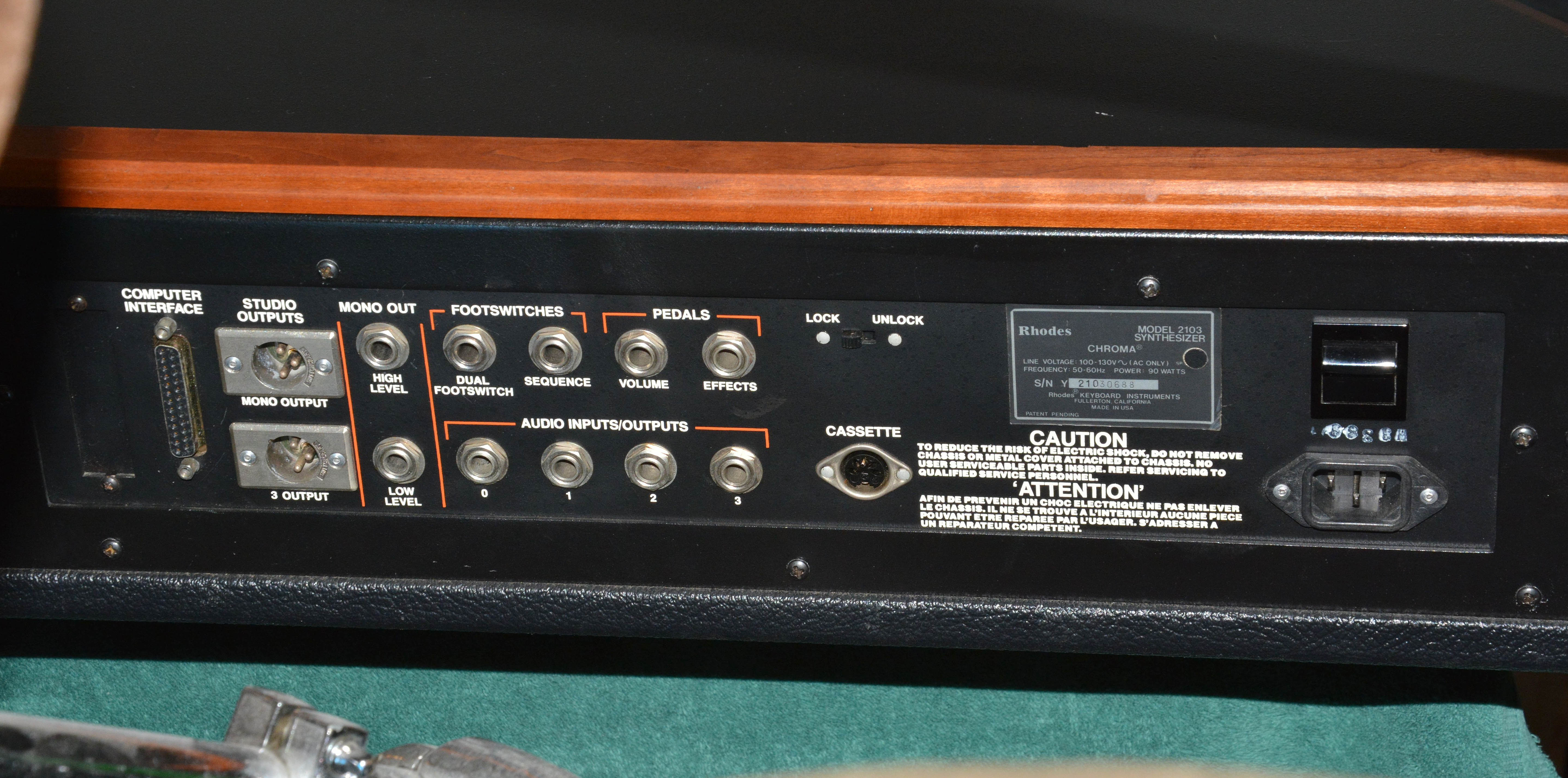
Lastly, below is the back panel. Gotta love the panel-mounted metal jacks, which are now very rare even on "pro" synths. Note the builder's plate/sticker, which gives a location of Fullerton, California. This brings up the question: where were Chromas made? As far as I know, Chromas were built in 3 locations: the first 50 were built by hand "in-house" in Wolburn, Massachussets, then production moved to the Gulbransen organ plant in Hoopeston, Illinois, and finally to the Fender plant in... Fullerton, California. See the 2002 interview with Philip Dodds and Tony Williams, and the 1993 Keyboard Magazine article The Synth That Survived ARP's Fall. From these articles, I get the impression that most Chromas were made at Gulbransen, and mine has a mid-range serial number, so I suspect mine was made there. Note also that Gulbransen and Fender were both owned by CBS at the time.
Links
| |||||||||||||||||||||||||||||||||||
| If you notice any errors or have additional information that you would like to add, please contact me! |