Peavey DPM3 SEDigital Keyboard
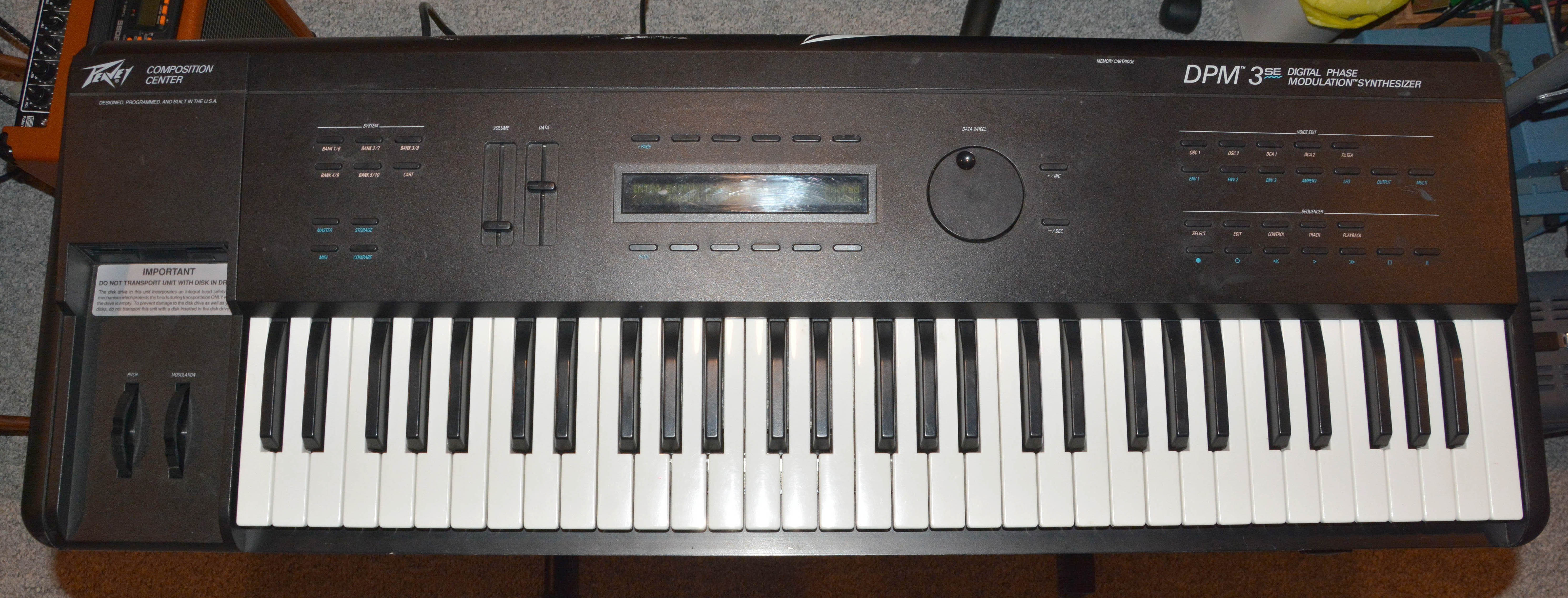
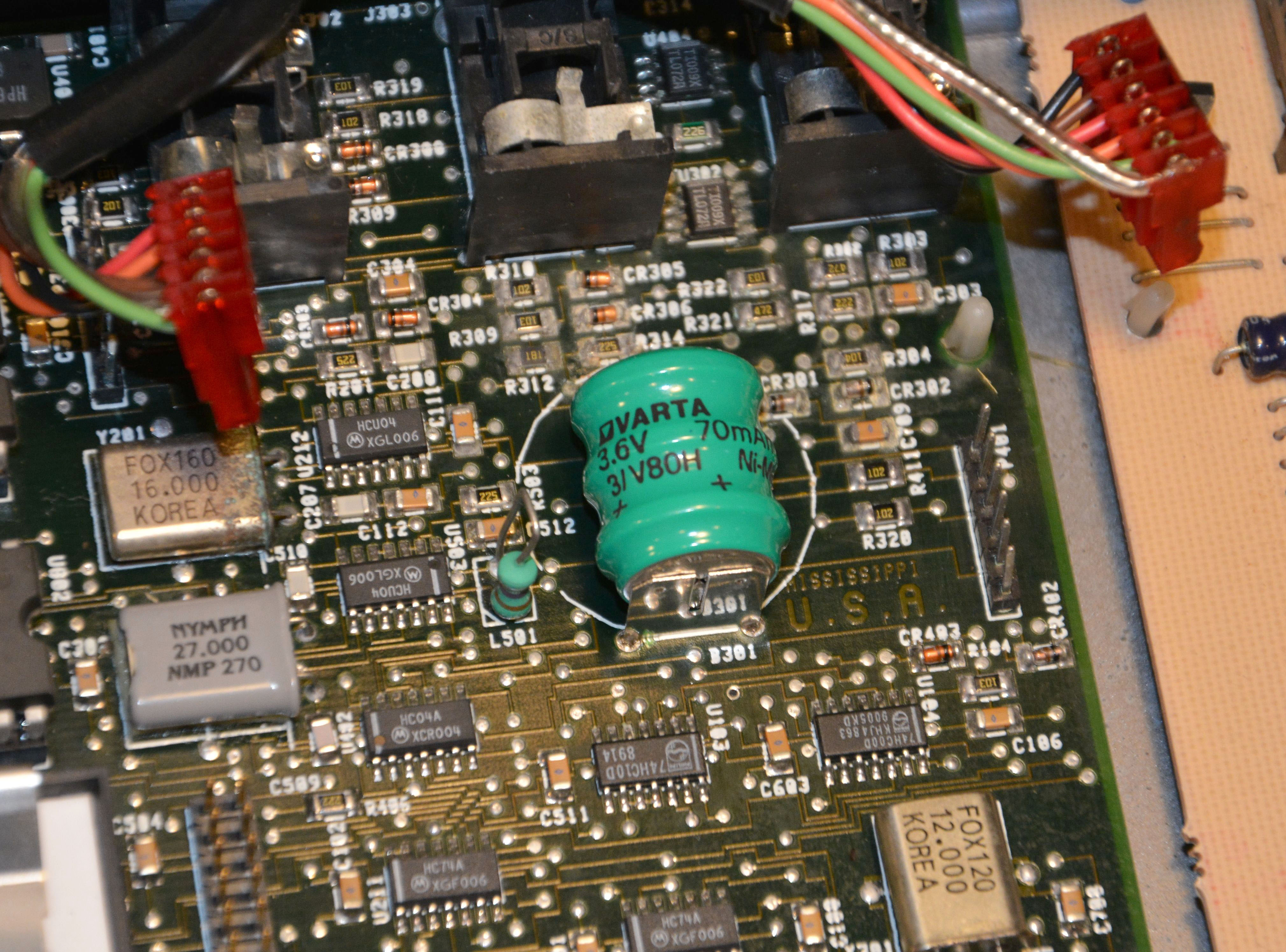
This article will describe my experience repairing a Peavey DPM3 SE keyboard in mid-2018. This keyboard is an early example of a digital synthesizer using DSP-chip-based synthesis—its sound generation and processing is basically "all software" and thus potentially modifiable (e.g. for different methods of synthesis), so Peavey marketed it as obsolescence-proof. This unfortunately turned out to be false, since Peavey quickly stopped making software for it after a few years, and they no longer repair them due to lack of parts. They also designed it with a poorly-placed battery that tends to leak and cause damage, as you will see. The DPM3 SE was introduced in 1991, and although many of its default patches are pure cheese emblematic of its time, it remains a relatively versatile instrument to this day thanks to its programmability... that is, as long as it works. This article will describe solutions to multiple problems never discussed before online, so I hope it assists in the repair of more of these instruments. This was a relatively extensive job, covering many probable failures. Note that I don't intend to provide an overview of the instrument's functionality or history, but I have included some sources of this info in the Links section. At this point, I have encountered two DPM3 SE units. Both came in functionally dead, displaying a blank screen, producing no output, and responding to no controls. I came across the first one early in my repair experience, and I gave up on it, since the battery leakage was severe; I presumed that something fundamental had been damaged by corrosion, since it was still dead even after a thorough cleaning. The second one, i.e. the subject of this article, also had terrible battery leakage:
Peavey's engineers placed the battery in just about the worst place possible, with so many thin traces and tiny surface-mount parts nearby. I must say: the soldered-in NiMH battery is certainly the worst aspect of this keyboard's design. In general, it is idiotic to use a "permanent" battery like this—not only should it be socketed for ease of replacement, it should be placed where it will cause minimal damage upon leaking. Either the designers knowingly reduced the instrument's longevity (i.e. planned its obsolescence, despite its marketing as obsolescence-proof) by using such a battery, or they were oblivious; the former is most likely. In any case, after clipping out the old battery, I cleaned up the corrosion above with isopropyl alcohol and some Electrosolve contact cleaner (which is just a mix of various solvents). An X-acto knife was used to carefully scrape away some of the hydride cakes. After the loose material was gone, I neutralized the area with some vinegar on cotton swabs, followed by more solvent cleaning. Here's the board after cleaning (and after installing the new battery, but just ignore that for now):
It looks much better; although some pads and traces are tarnished, nothing seems to have been really damaged. Yet, the instrument was still dead after cleaning, just like the first one. This time, however, I found and downloaded the schematics (look on this page), and really got into it. When something is as functionally dead as this thing was, the first thing to check is the power supply. Sure enough, multiple problems were evident.
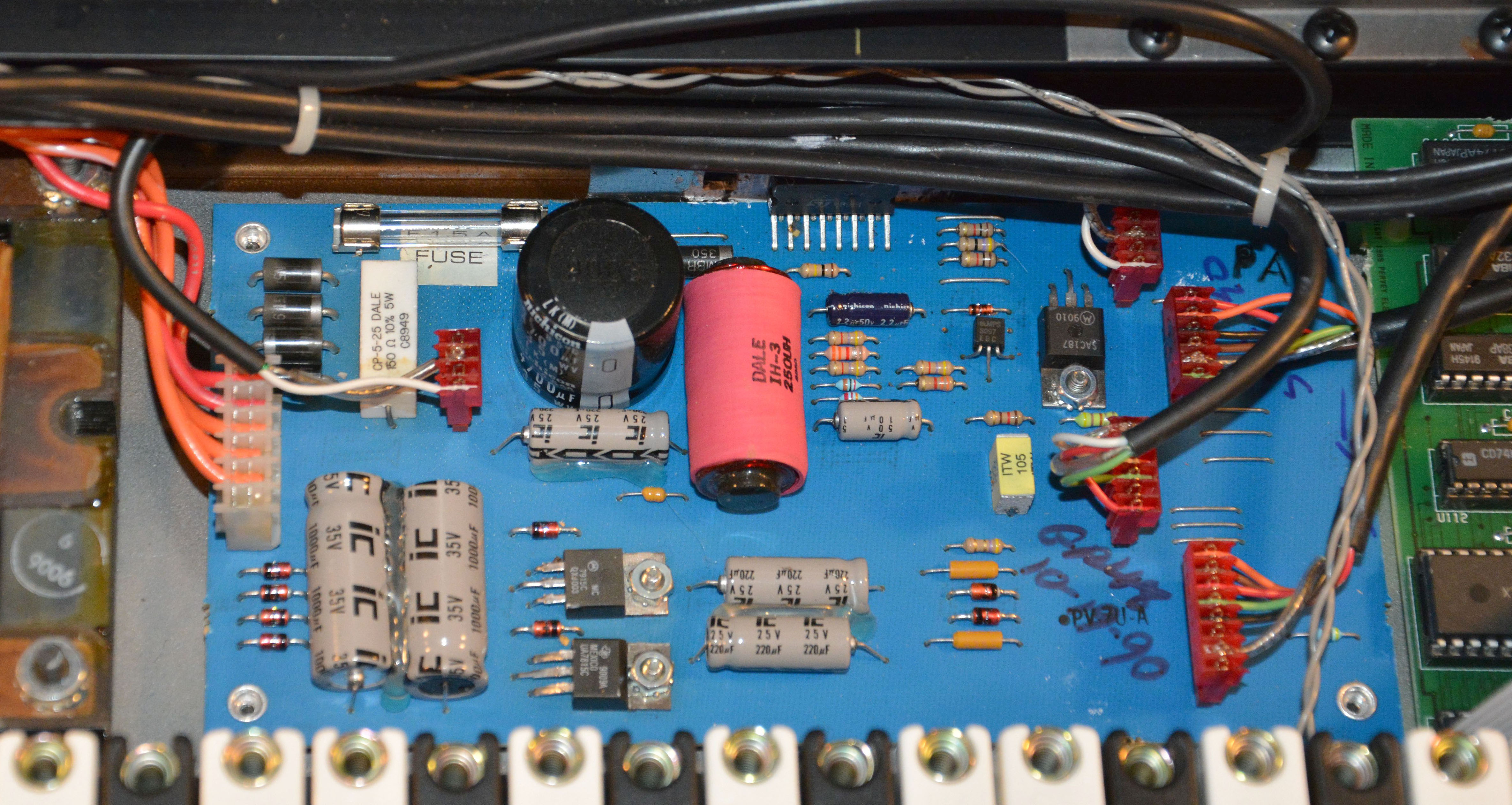
This is the power supply board, which gives three each of regulated and unregulated voltages, and has a nice spacious through-hole single-sided design. The first issue was that the 1A fuse in the upper left was blown; this fuse sits between the upper bridge rectifier circuit and the input to the L296P switching regulator chip, mounted to the big heatsink under the wires (using a metal clip that was removed prior to the above photo). This chip is very important, outputting the +5V regulated supply, so of course, if the fuse is blown, the +5V rail would be dead, and nothing would work since the digital circuitry is powered by the +5V rail. Replacing the fuse, however, didn't change anything. The output of the L296P chip still measured nil, at -0.04V. You might guess that the fuse blew again, but it didn't. So, after a few checks of the surrounding components, the L296P was determined to be at fault. It even had a small burn-mark on pin 3, perhaps where a previous tech had shorted it to something! (It would explain the blown fuse, since pin 3 is the chip's input directly following the fuse.) In any case, the chip is still in production as of August 2018, and thus available from reputable sources such as Digi-Key, but I didn't want to place an order just for the chip (since shipping is flat up to an order of $100), so I searched on eBay and found a French seller with a good price including shipping. The listing can be found here, as long as it hasn't expired yet. The chip arrived in less than two weeks, well-packed and genuine. Note that whenever possible, I avoid the numerous eBay sellers located in any part of China, including the People's Republic, Republic of, and Hong Kong. This is mostly because shipping to Canada tends to take over two months by the usual "free" economy service. As well, Chinese sellers in particular are known for a high proportion of fakes and duds: counterfeits, rejects, pulls (sold as new), and so on. I have received counterfeit and defective parts from Chinese sellers, whereas I've never received counterfeits from elsewhere, and all of the defective new parts I've received from non-Chinese sellers originated in China. They are also cheap and sloppy in their packaging, resulting in damage such as broken pins, and my favorite, broken LCD screens. The seller that packed an LCD so badly it arrived cracked has apparently re-sent it twice now, yet nothing has shown up in over five months! After multiple incidents like this, I no longer trust them. Anyway, replacing the L296P chip is relatively easy. A few tips:
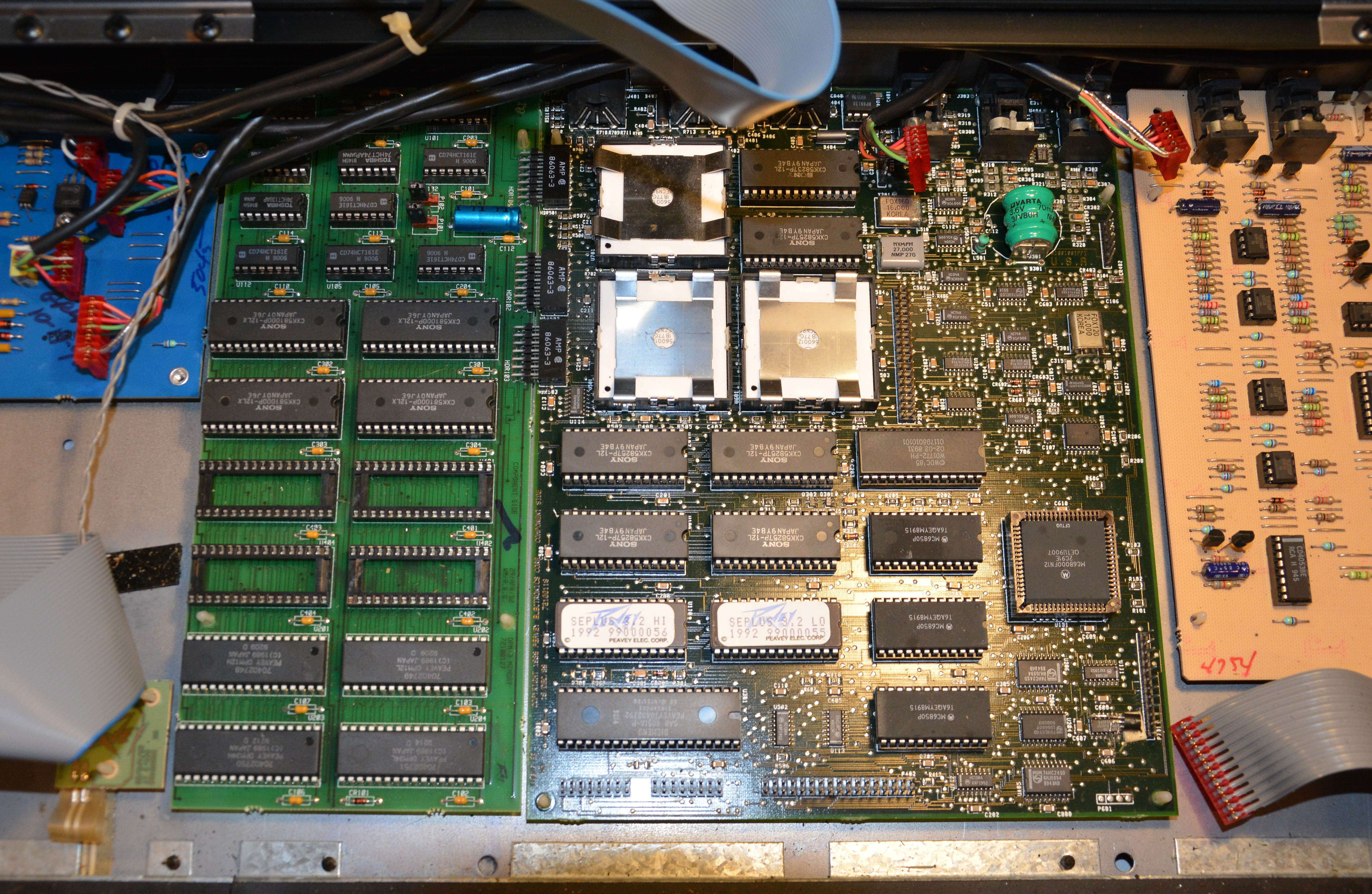
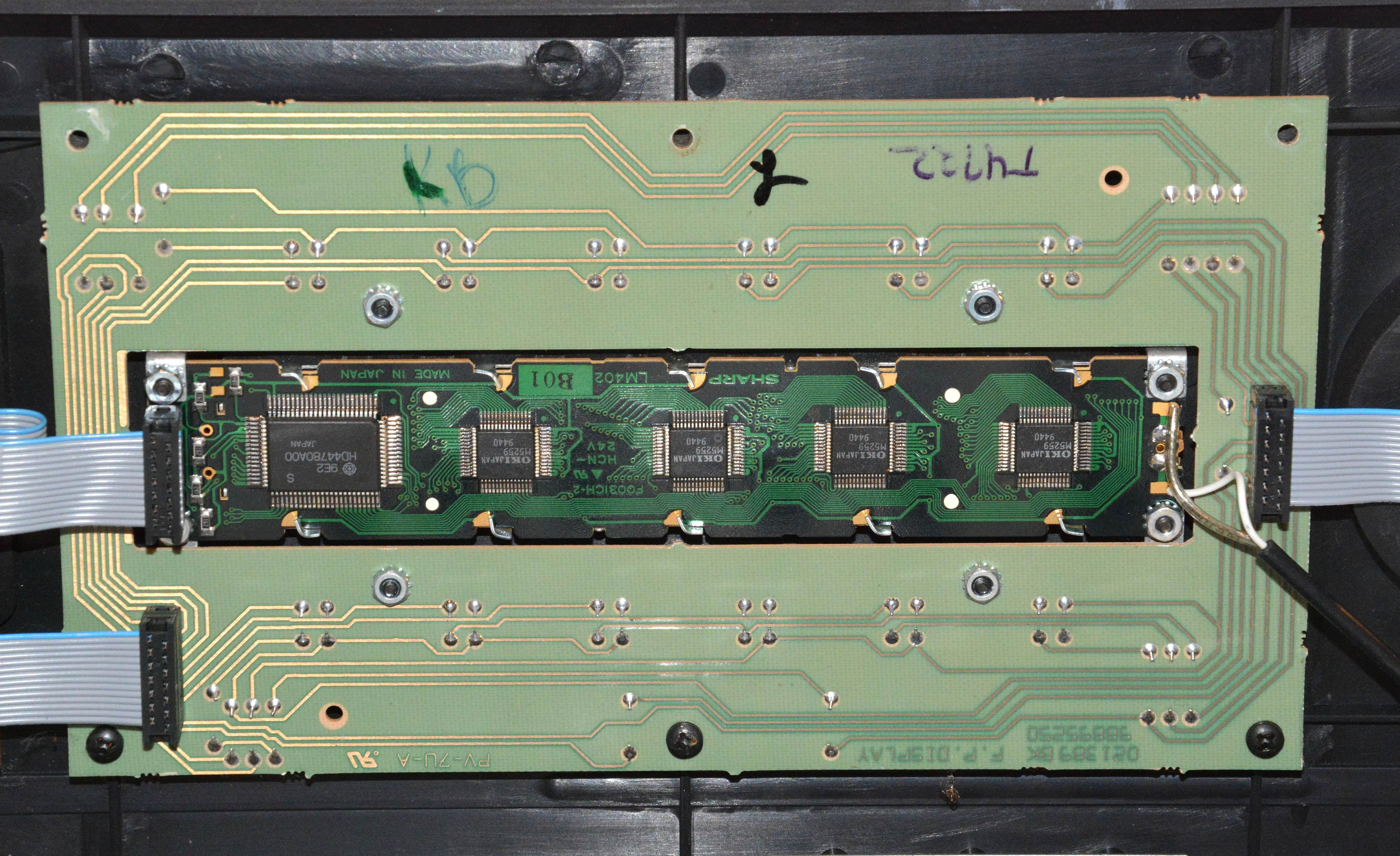
Once the L296P was replaced, the keyboard booted properly. It was a glorious moment, since I wasn't sure if it would boot without battery voltage, and I didn't want to buy a new battery before ensuring it was otherwise functional. Note that without the battery, all of the patch data was corrupted, showing gibberish names, and producing no sound when playing the keyboard. But, with such encouraging signs, I ordered a new 3/V80H battery from a Canadian seller here. The 3/V80H is a fine subsitute for the original 3/V60R as long as it is has the same 3-pin footprint—don't buy the 2-pin version. Installing it was a pain, since removing the processor board is difficult. You have to remove the entire keyboard by means of 12 screws on the bottom, then disconnect 6 connectors, remove the four screws holding the jack panel to the back, and then pop every nylon clip in order to lift out both the processor and memory boards. You can see these boards below, which are joined by three headers. Note that the operating system ROMs have DPM3 SE+ firmware—in fact, the sticker on the bottom with the serial # calls the unit an SE+, even though the top panel shows plain SE. I suppose it ought to really be called an SE+.
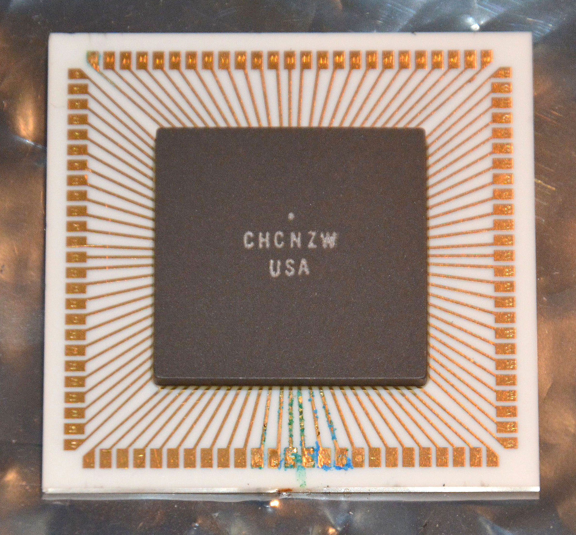
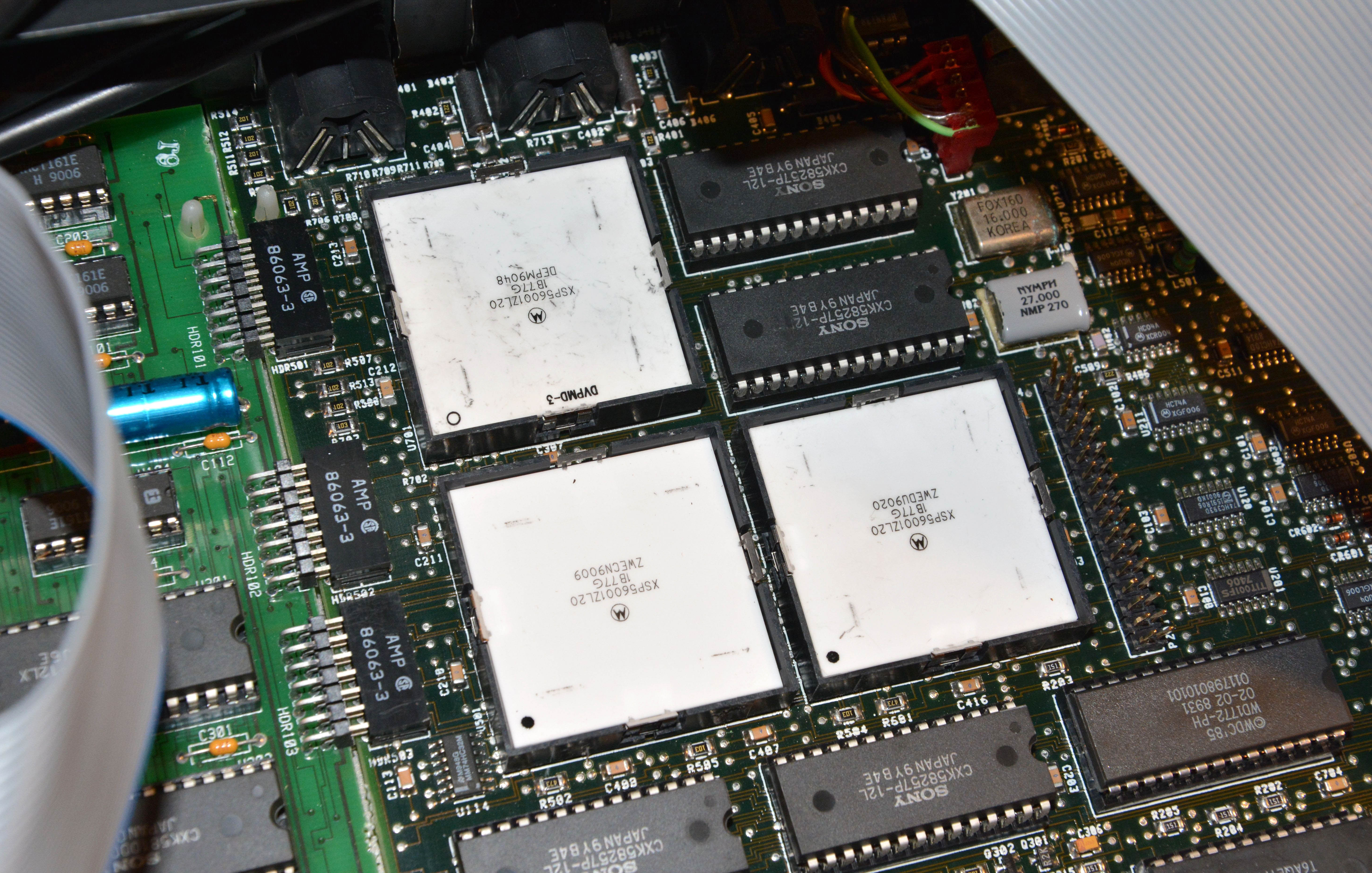
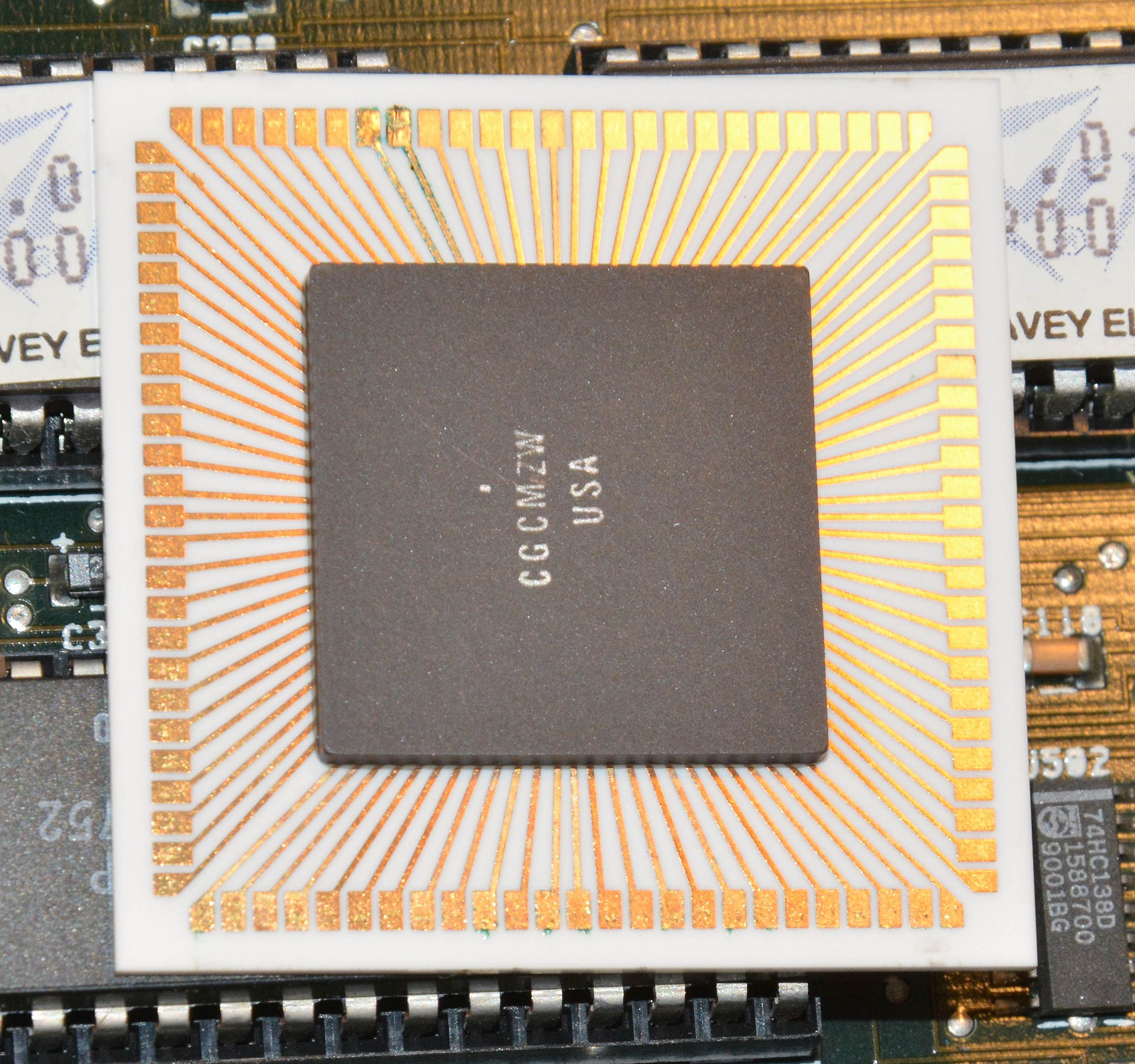
Interestingly, the solder joints holding the leaky battery were bulbous and flux-covered, suggesting that the battery had already been replaced before! I think the lesson here is to keep your battery charged by playing the keyboard often! Batteries are most likely to leak when they're dead, and the battery only charges when the keyboard is powered, so keep that in mind. Note also that if the battery hasn't leaked too badly, it may be possible to desolder from the top side, but in my case, the corrosion on the pins was too severe to be able to do this. Make sure to use ESD protection and general care when handling these boards, which hold extremely rare chips. Once the battery was replaced, I had to re-load the original data for "programs" (i.e. patches), effects, and sequences onto the instrument, since this data is not stored in ROM. Peavey still hosts all of the files here under the DPM 3 heading. Once downloaded, they must be transferred to a 720KB / Double Density 3.5" floppy disk. This can be difficult today, since not all USB floppy drives are able to use 720K disks, and such disks are rare. A solution to the latter problem is that, as long as you have a suitable drive, you can tape over the bottom-right hole and re-format a 1.44M disk as 720K if you don't have a proper 720K disk. For me though, I ended up putting the data onto a 100MB Zip disk via a drive with USB, then bringing out my Power Macintosh G3 and using it to write from the Zip to a 720K floppy. From this floppy disk, the data loaded perfectly into the keyboard's memory and stayed there, indicating a successful battery replacement. The instrument also produced sound at last! However, problems still existed. For one, the lowest key didn't trigger any sound, so I had to remove the left PCB on the underside of the keyboard and clean the offending contacts with isopropyl alcohol. That was an easy fix, but the next problem wasn't: sometimes, the output would sound harshly distorted, as though there were corrupted bits in the sample data. I noticed that for certain patches, the first four notes held would sound normal, but the four after that would sound terrible. Just in case it was a connection problem, I re-seated and cleaned the pins of all of the socketed DIP chips, especially socketed memories. This didn't help, so I then suspected bad memory chips, or problems with one of the two sound-synthesis DSP chips. The normal process for checking complex chips like these would be to just start swapping them, replacing suspect parts with known or likely good ones. However, it was not necessary to do this, because... As a product of their kind hearts, Peavey made a diagnostics program that can easily test the DSP chips and all of the memory. You can find the program and the guide for it here. It is small enough to fit on the same floppy as the DPM3 programs/effects/sequences. I should also mention that in all, the unit has three DSP chips: two for sound synthesis ("DSP1" and "DSP2") and one for effects processing ("Effects DSP"). All three are the same type: Motorola XSP56001ZL20, of the famous 56000 family of DSPs, and housed in beautiful square white ceramic packages that are socketed. In any case, running the diagnostics program, the "WvMem" test failed every time (with the DSP2 ROM test showing incorrect checksums, yet DSP1 showing correct checksums looking at the same ROM), and the "FxRAM" test failed once out of the ten or so tries. Considering the the ROM checksum discrepancy (which indicated that the ROM was good, but DSP2 was suspect), and the Effects DSP failure, I then suspected problems with these chips, for example: dirty pins, bad sockets, or internal failure. On the processor board, they are held in place first with metal clips, which must be carefully pried out and lifted off; a dental pick has a suitable hook for this. Then the clips around the edge of the chips can be disengaged, and the chips removed. Here's what the Effects DSP looked like:
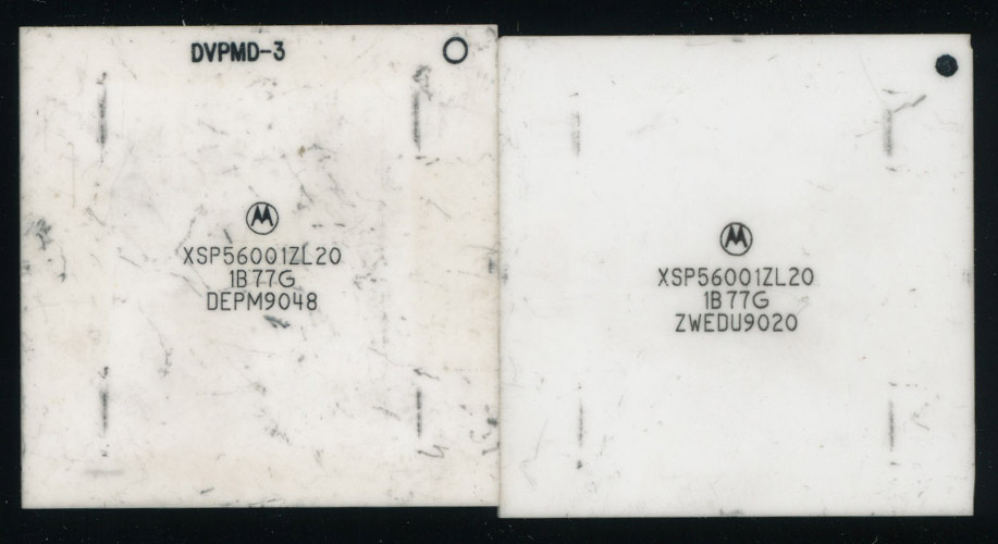
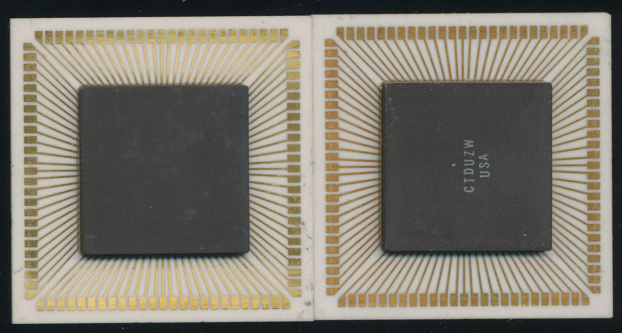
The area of severe blue-green corrosion was nearest to the battery, by the gap in the socket's plastic for the edge clip. Damn you, corrosive vapor! It's a miracle that this chip passed the FxRAM test all but once! However, the corrosion had eaten under the gold plating of the traces, and so sections of plating flaked off when I tried cleaning, truly ruining the chip. Checking the others, the DSP1 was fine, as expected, but the DSP2 had one corroded trace that measured 379 ohms. I tried to bridge it with an extremely thin jumper wire, but it then behaved even worse in the WvMem test, probably because the thickness of the wire was causing connectivity problems in the socket. Even if it worked, I wouldn't trust it as a long-term fix. Maybe in the future I could try a conductive pen. This would be the point where most technicians would really give up, and I must admit, I came close to doing so. The XSP56001ZL20 is very scarce at this point, having been out of production since the early 90s as far as I can tell. I found only one eBay vendor, pricing at about $50 CAD per chip, plus $50 shipping—what a joke! I then searched other websites, but found that many of the companies claiming to have the chip did not list prices (instead using the quote request system), and in fact, many looked to be fraudulent, with fake addresses and unbelievably large amounts of stock. I found two that upon further investigation appear to be front organizations, possibly for organized crime in New York, no joke—email if you want more details. Eventually though, I was able to source two replacement chips (the only two he had) from John Culver of The CPU Shack Museum in Oregon, at a reasonable price. Thanks John! He also confirmed that the different color variants of the chip both use the same die, so although he did send two white ceramic ones, the gray ones would also work fine. He also suggested the conductive pen idea for fixing the existing chips. In any case, here are the two chips he sent me:
And here they are installed in the instrument (right and upper left):
Finally, all diagnostic tests passed, and the instrument was completely working! So, to review, here's what it took to bring this exceptionally troublesome instrument back to proper operation:
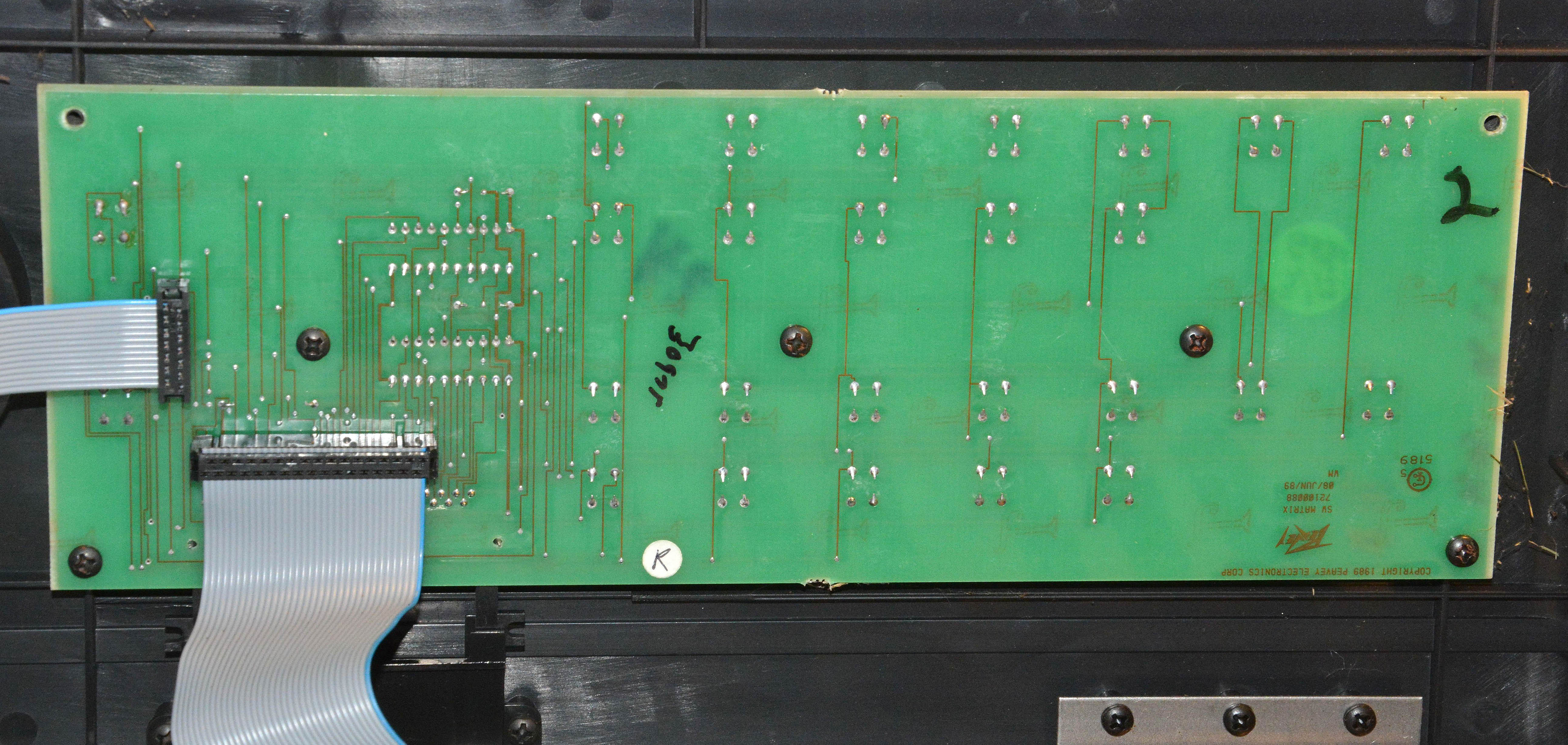
All in all, it took 8 hours and 12 minutes of labour, and $72.26 CAD in parts. Was it worth it? I think so, though its worth will still have to be proven with use. Although I prefer analog keyboards, this one has a unique enough character that I consider it worth saving, especially because of its versatility in patch editing. In any case, I always enjoy these long repairs which involve plenty of thought. Some long repairs are only such because you have to replace many parts that you already know are bad or unreliable, such as wax paper capacitors. Not this one — I only replaced parts that were certainly bad, and it still took a lot! I hope this article has been interesting, and that it will help others in repairing such instruments. Addendum 10/16/2018: There have been two noteworthy developments since first publishing this article. Firstly, John Culver of the CPU Shack Museum (from whom I got the replacement DSP chips) has published his own article called Peavey and the Motorola DSP56000, which explains some background of the 56000 series chips, and refers to my DPM3 SE repair. One especially interesting fact mentioned is that Peavey influenced Motorola's design of the 56000 series from the start. I couldn't find any other online reference to this, so I asked John where he learned it; the source is the book The Peavey Revolution by Ken Achard. The internet does not know everything! Secondly, after only a few hours of playing this keyboard, the middle-right "soft" button above the screen completely stopped working. These plastic buttons depress PCB-mounted tactile switches, and I noticed earlier that some of these switches were not working perfectly, but I left them in place, since they were still usable. However, with the complete failure of one, I decided to replace four of them: two that were electrically faulty (including the failed one), and two that were mechanically faulty (not giving the proper click response). I am not a big fan of tactile switches, because they often fail prematurely, and never improve with contact cleaner once they lose electrical contact. They can also lose their click, and sometimes both click and contact. At least they are plentiful and standardized, so I swapped the faulty ones with my usual replacement type: Digi-Key part number SW402-ND, which is Omron part B3F-1020. Omron is a reputable Japanese manufacturer, and the switch is rated for 1,000,000 cycles—the most durable I've found. It is the correct 6 x 6mm footprint, and 5mm height off the board. The operating force of 100gf is not critical, though it does feel slightly weaker than the originals. However, if you look at the other members of the B3F series (B3F-1022, 1025, and 1026), the rated durability decreases dramatically with increasing operating force—the B3F-1026, with operating force of 500gf, is rated for a mere 50,000 cycles. The next step from the B3F-1020, the 1022 with 150gf operating force, has a life of only 300,000 cycles. So, I think it's a good compromise. I've also used the SW402-ND to replace a faulty tactile switch in a Roland Juno-106, in which it felt indistinguishable from the originals. Replacing the switches gave me a chance to clean the display, on which dust had settled. As well, I took a few pictures of the top boards, which may help as reference to someone. Notice that the boards all have different substrate materials and solder mask styles, and the middle board is single-sided while the others are double-sided—I have no idea why the boards are so inconsistent overall, but it does make things more interesting. Also notice that the display assembly is a 40x2 character type using the HD44780 controller chip, which is still standard to this day. This should make it easy to replace if it ever fails, though finding a green-on-black version may be tough.
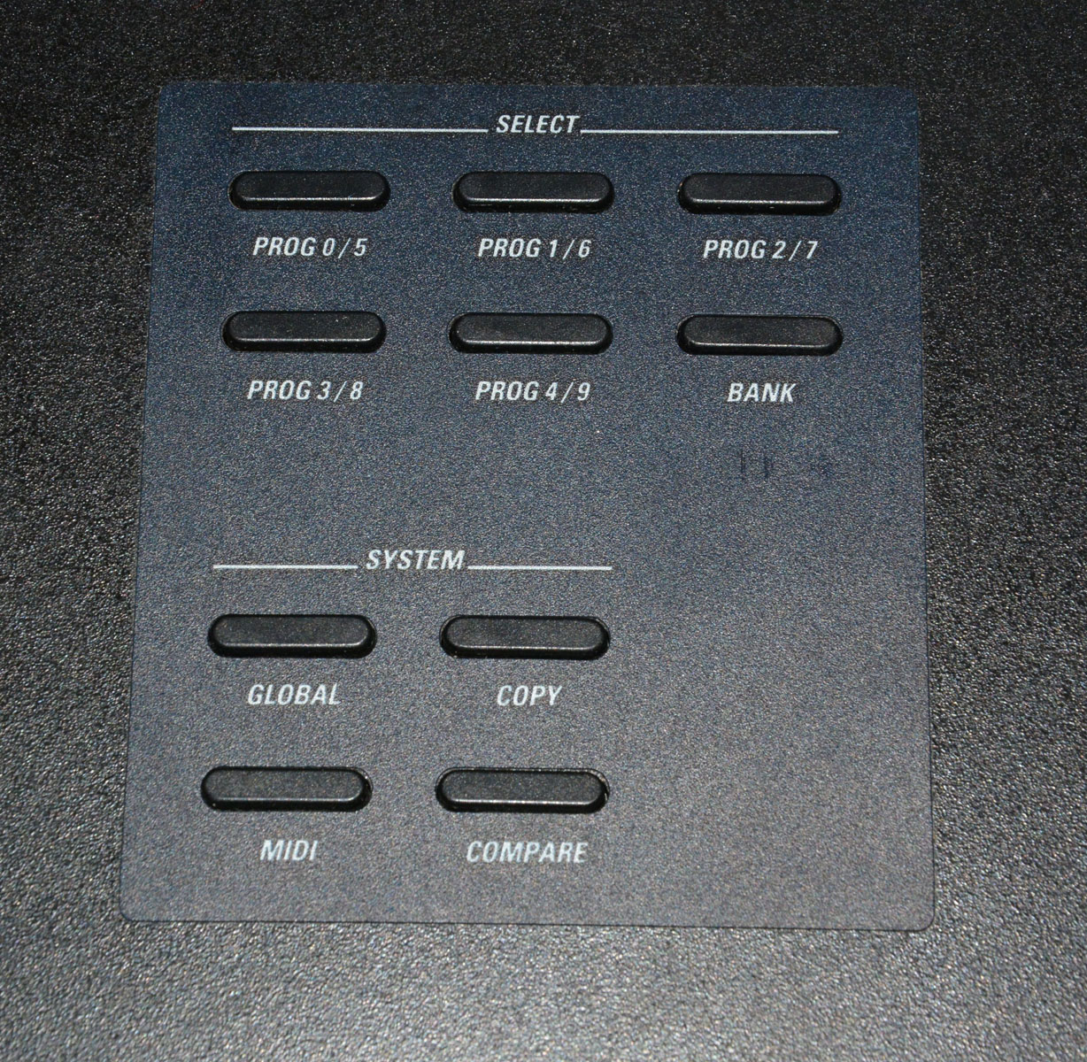
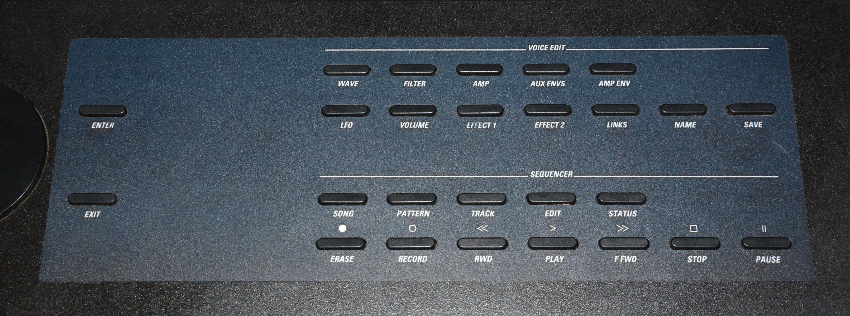
A final note: I also noticed that the floppy drive was loose on the left side. This was caused by missing mounting screws on the bottom of the drive, which hold it to a 90-degree mounting bracket. I put in some new screws (M2.5 thread), and finally, it was back to making music! Addendum 6/26/2019: Since the last update, I have received many favorable comments and inquiries as a result of this article. One such inquiry led to repairing another DPM3 SE for a customer in British Columbia, which is what I'll talk about in this addendum. Actually, although his instrument started as a DPM3 SE+ like mine, it was upgraded to a DPM4 at some point. From what I can tell, the upgrade simply consists of replacing the two operating system EPROMs, replacing the memory board with a DPM4 type, and installing thick plastic stickers on the top panel to indicate the new functions of the buttons. With these changes, the polyphony is increased from 16- to 32-voice, the sample ROM is "more than doubled" to 10MB (with a socket for a 2MB expansion chip), and the maximum sample RAM increases from 512KB to 1MB (i.e. from 3.25 to 6.5 seconds), among other things. For more info, see the DPM4 manual, which can be found on this page. Here's what the top panel looks like with the DPM4 labeling, with my unmodified DPM3 SE shown below for comparison:
Like my DPM3 SE, this was a big project. Below is a list of all the repairs done, followed by further explanation of the most important ones:
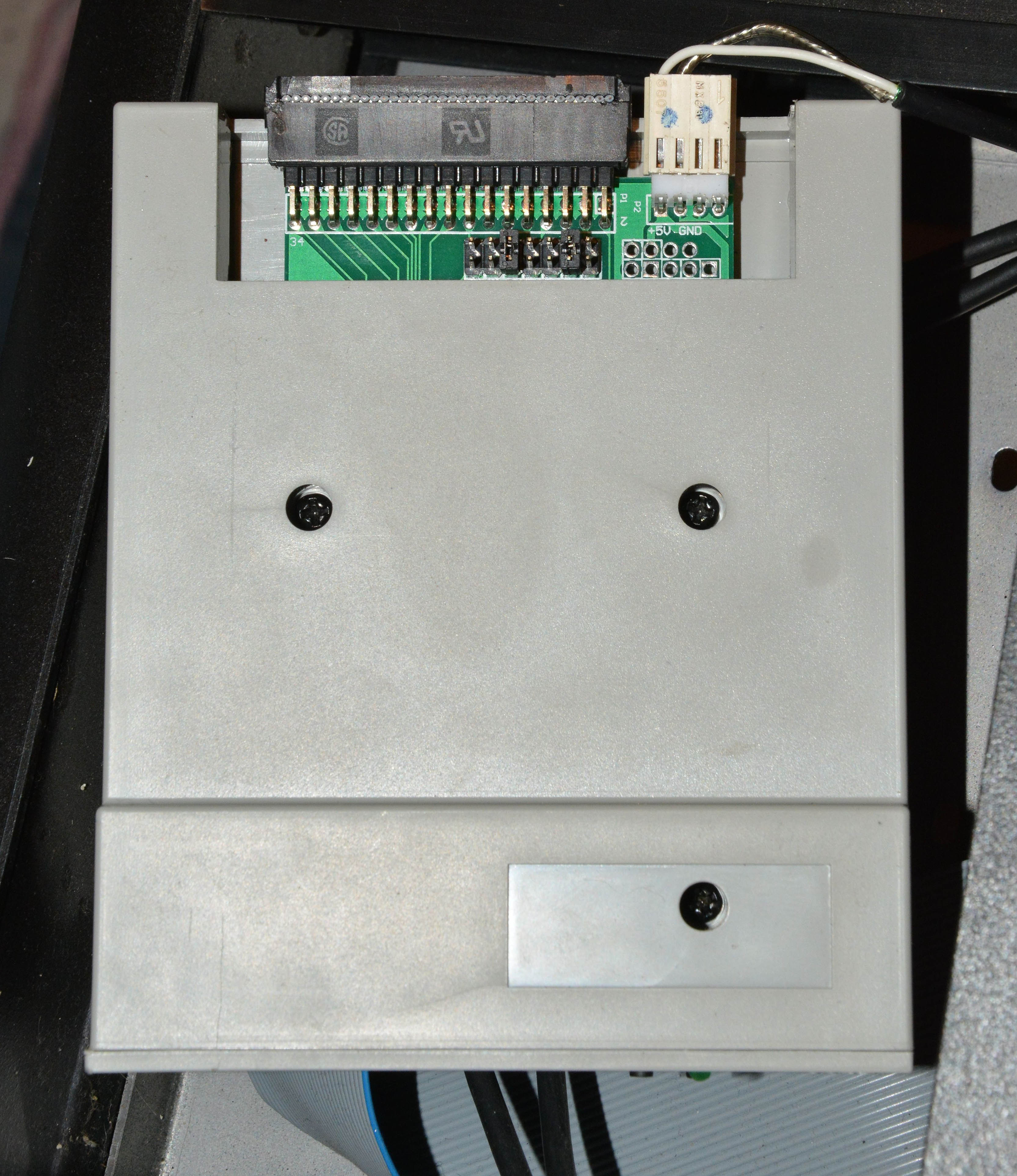
The first important mention is that the Gotek SFRM72-FU-DL "floppy to USB emulator" works in this instrument — this unit was provided by the customer, and is specifically made to emulate a 720K floppy drive. Gotek sells many different types of floppy emulators, which use USB flash drives as the storage medium. Up to 1000 virtual disks can be accessed on a single flash drive; in this case, a 1GB stick is more than large enough, since it can store the equivalent of 1,450 720K floppies. It was also relatively easy to get working; I simply installed it in place of the original drive, and it worked when following the manual's somewhat puzzling instructions. The drive looks like this:
The SFRM72-FU-DL is only available in grey, although the SFRM72-TU100K appears to be the same except black, though in some pictures it has only two 7-segment digits. I haven't tried it, but it would probably work as well, and it would be a better cosmetic match. In any case, for those with no ability to write to 720KB diskettes, or with a dead original floppy drive, "emulators" such as this provide a solution. However, besides that it technically works, I was not impressed at all with the quality of the device. I was so unimpressed that I decided to write a list of every fault I could name:
As well, despite the poor design and cheap build, the SFRM72-FU-DL costs about $40 CAD or more. Although the original type of floppy drive is scarce (Sony MP-F11W-5WD), it may be cheaper to find a 1.44MB drive that can be set to work in 720K mode, such as the Teac FD-235HF, which often sells for less than $20 CAD. I can't confirm that this would work, but it seems possible based on this site. As well, although Gotek has a near monopoly on the floppy-emulator market, I've found one other type, called the HxC, which is clearly of higher quality both in design and build (particularly the Lotharek version), but costs about $225 CAD, meaning it is much less economical than replacing with another floppy drive. Of course, it may also be possible to fix some problems with broken original drives. Anyway, once the floppy emulator was working, I was able to load in DPM4 patches and listen to the synthesis. All seemed good at first, but then I noticed that a harsh "crackling" distortion was sometimes heard, similar to my instrument when the DSP chip leads were corroded. Well, sure enough, all three DSP chips showed some corrosion of the leads, all thanks to the alkaline fumes from Peavey's ridiculous battery! Here's the DSP2 chip prior to cleaning, which was the worst of all:
By some miracle, none of the traces were completely eaten through, so I was able to simply clean them with isopropyl alcohol without destroying the chips. I also cleaned the sockets, since some showed a little bit of green residue. The synthesis and effects then sounded fine when I reinstalled the chips. I couldn't do a proper DSP test like I could on my DPM3, since with the DPM4 operating system, Peavey switched to a built-in diagnostics program that is only able to test the front-panel controls as far as I can tell — I wasn't able to run the diagnostics program from disk. I'd be grateful for more info about this, since I wonder if the built-in program is more capable than it seems.
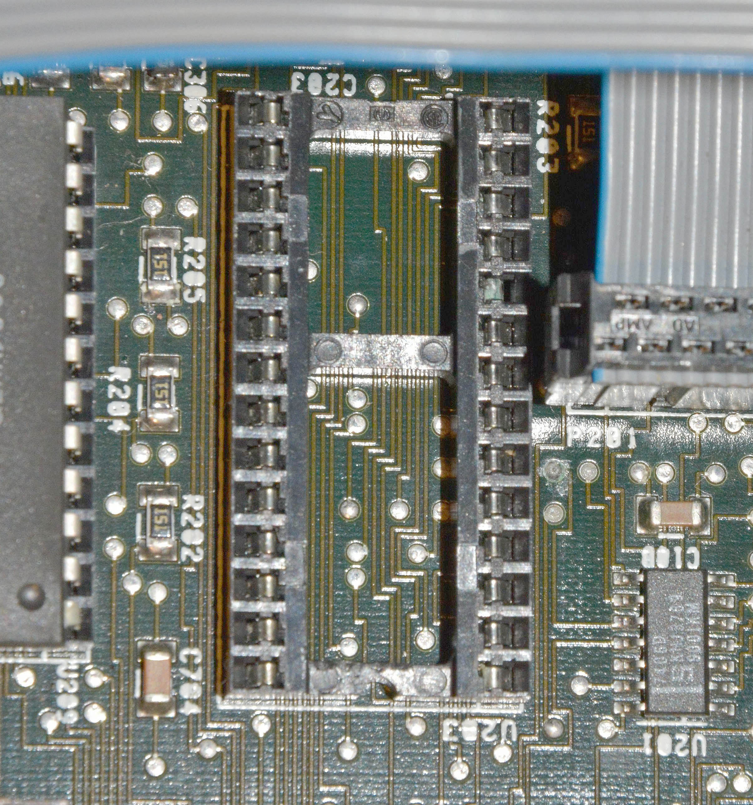
Shortly after I loaded the patches and noticed the synthesis problems, the floppy stopped working; at first it would give various different errors, but eventually settled on always giving "TRACK SEEK OPERATION WAS UNSUCCESSFUL" whenever a read or write operation was tried. After extensive troubleshooting, I found that pin 10 (one of the data lines) of the floppy controller chip U203's socket had corroded and broken in half. You can see it 5th down from the upper-rightmost pin in this picture:
Another battery-fume casualty! Now, replacing a 28-pin DIP socket is not the easiest task on a double-sided board with extremely small circular pads with plated-through holes. The best method probably would have been to use a solder-sucking iron, but since I didn't have one, I used a normal iron with solder wick. Most of the pads unsoldered without trouble, but because it's almost impossible to remove all solder from a plated-through hole no matter what you're using (especially when you only have access to one side), five pads peeled off on the top side upon removing the socket, including two with traces. In the case of these, I ran jumper wires from the nearest vias (which thin wires can be soldered into) directly to the new socket's pins on the underside. This fixed the floppy problem. So, if you're having floppy issues, absolutely check the socket of the controller chip, as well as the floppy connector and the other (mostly surface-mount) floppy circuitry, all of which is quite close to the battery. All in all, this one took even more effort to bring back to life than my own instrument. I must admit, I've become significantly more annoyed by Peavey's idiotic design with the battery as a result of this repair. Besides the tactile switches (and even then, who can say for sure), every significant problem on this keyboard was caused by battery leakage. Maybe these keyboards really do deserve to die early, given their flawed design? Yet, whenever I think that, I consider the joy I feel after repairing something destined to fail prematurely. It can be quite rewarding, so long as the device has virtues that make it worthwhile, which I consider to be the case with these DPM keyboards. As well, in fixing things like this and returning them to their owners or selling them, I know I may be eliminating the sale of a lower quality and less serviceable unit, as are the vast majority of keyboards made today. If you don't know what I mean, just wait a while, since I'll be explaining it in an upcoming article titled "What's Wrong with Modern Electronics"! Addendum 5/15/2020: In late March of 2020, I received three DPM3 mainboard sets from a customer in the U.S., along with various other parts. The objective was to repair at least one of the boards. Unfortunately, this job turned out to be a complete bust. The "best" of the three boards, with no visible battery damage, was unable to read from floppies, always reporting "drive speed above tolerance". This was true even with a known-good floppy drive, cable, controller chip, and seemingly all-good supporting components (R203–R205 and all sections of U201). As well, this board would often report "DSP powerup failure" despite all-good DSP chips. Swapping all ICs with known good ones made no difference. You may ask "why not run the diagnostics program?" Because it is loaded from floppy disk, that's why! What a ridiculous design — having the diagnostics on a floppy, which of course requires the floppy system to be working, besides 90% of the remaining hardware! With that mainboard looking hopeless, I moved onto the 2nd-best board. This one had suffered mild battery leakage, but nothing appeared ruined. All IC sockets looked fine, and none of the DSP chips were corroded. Yet, this board always gave a blank LCD readout. Knowing I had a good power supply and memory board, I next checked the clock circuits. Surprisingly, the section of the surface-mount chip U211 that divides the 16MHz clock down to 8MHz was bad (its output stuck high), resulting in missing 8MHz, 667kHz, and 500kHz clock signals. I replaced it with one pulled from the worst mainboard (which had serious battery damage, and destroyed pads and traces from sloppy rework), and this fixed that group of clock signals. But it still gave no display on power-up, so I then checked the 27MHz clock circuit, and found that section B of U503 (buffering this clock) was bad, with very low output, resulting in no 27MHz clocks either! I desoldered and replaced it with a chip from the worst board again, and then the 27MHz clock signals were restored. Yet, the display still showed nothing. I swapped all of the socketed chips with known good ones. No improvement. At that point I called it a day. Even with three mainboards to work with, and a working DPM3 for parts and comparison, I was unable to make one working board within a reasonable amount of labor. Also, since December of 2019, I had been trying to sell my own DPM3 SE. In mid-May of 2020, a serious buyer finally came along and set up a meeting. Shortly before his arrival, I powered the instrument just to make sure everything was still OK. Well, it ran for about 5 minutes, then gave an "ADDRERR" message and a lack of response to any buttons (despite that it said "press any button to continue"). No amount of power cycling would clear up this error. So, I called off the sale. I later found that by reseating some chips and connectors, the error went away. However, at that point I no longer trusted the instrument enough to sell it — I didn't want it to fail quickly in the hands of the next owner. So I decided to scrap it and sell the parts as-is. The mainboard will be going to the aforementioned American fellow, and most of the remaining parts will appear on eBay. At this point, I no longer accept Peavey DPMs for repair. Servicing them is simply a crapshoot, due to the insidious problems caused by battery leakage, plus the inherent difficulties of obscure ICs, surface-mount parts, and diagnosing very complex digital designs with limited documentation and limited customer budget. Fixing these instruments must be done as a labor of love, and I no longer have any love for such things. My personal interests have shifted away from digital and IC-based keyboards, and towards vacuum-tube and discrete transistor ones, which are truly the best in terms of serviceability and build quality (besides sounding better), and which are thus most worth preserving. The DPM3 is not made to last, and I should also mention that in the end, I never loved any of its sounds, despite working with them for months during practices. They are mostly the sorts of cheesy (and blatantly "digital") imitative timbres common to the 1990s, which is my least-favorite decade of the 20th century in terms of music. I also never discovered any exciting sounds via patch editing, though admittedly I didn't spend that much time experimenting. And the physical design is nothing beautiful — the usual black plastic and metal, featureless except the text all over. At least it's better than modern keyboards, in that the body is roughly half aluminum (the bottom and back portions), and at least most chips are DIP and socketed instead of surface-mount. Links
|
| If you notice any errors or have additional information that you would like to add, please contact me! |


First Published: 09/07/2018