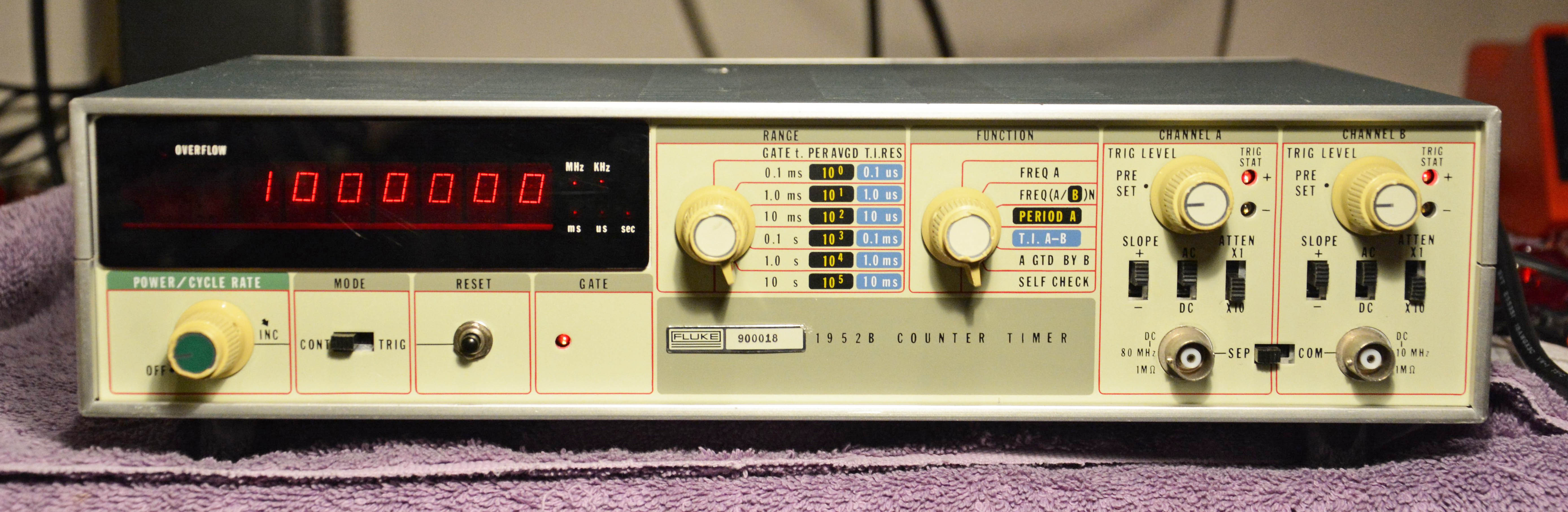
Fluke 1952BCounter / Timer
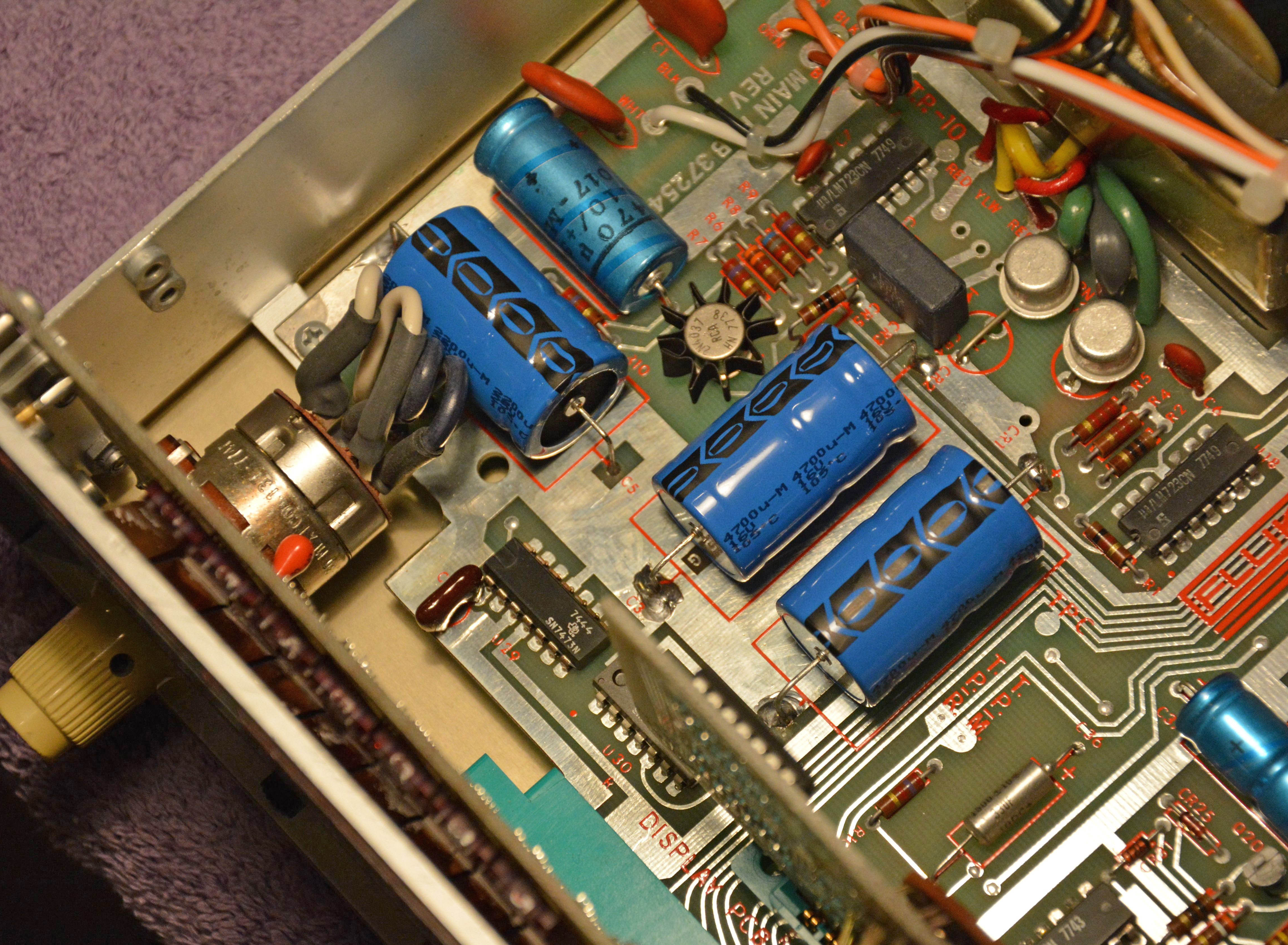
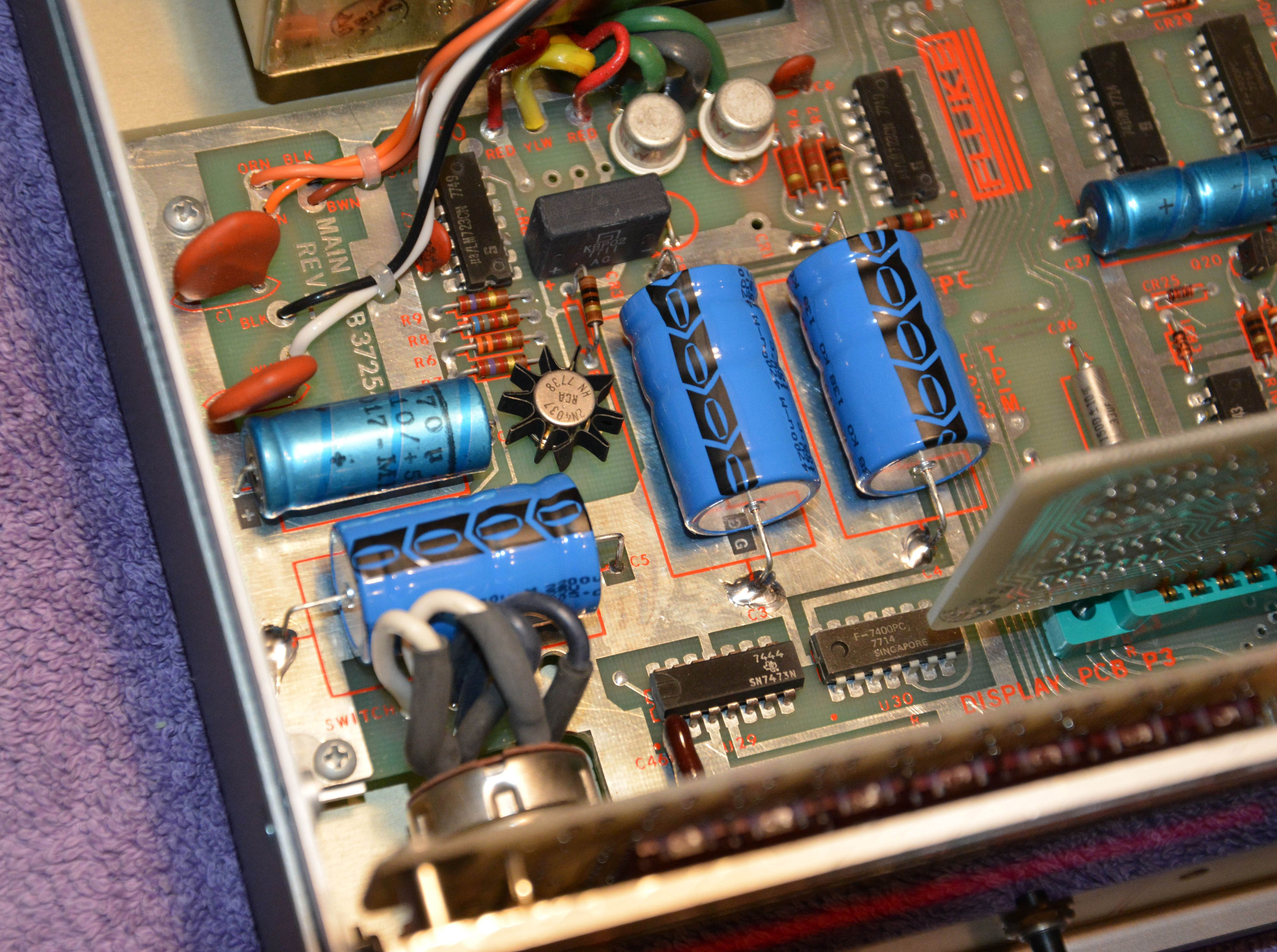
This is a neat little American-made frequency counter and timer introduced in 1975 (based on the date in the manual), with my unit manufactured in 1978. Information is scarce, but from what I can find, the 1952B was among the first frequency counters made by John Fluke Mfg. Co., with the 1950A, 1952A, and 1953A being part of the same series, and only the 1941A (featuring a nixie-tube display) preceding this series. Smaller and plastickier units followed, such as the 1900A and 1920A, which are housed in similar plastic cases to the popular 8000A digital multi-meter introduced in 1976. Of course, Fluke is now known primarily as a manufacturer of DMMs, and no longer produces standalone counters. They are also no longer a standalone company, being bought by conglomerate Danaher in 1998, which spun off Fluke and other subsidiaries in 2016 to create Fortive, another gigantic conglomerate, which also owns Tektronix. I will skip discussing the device's functionality, since it is a fairly standard counter; suffice it to say that the input frequency range is DC to 80 MHz, and the rest you can more or less figure out from the front panel. The main purpose of this article is to show how simple and economical many test equipment repairs can be. In fact, I've also repaired two earlier counters quite easily with very similar problems: the Beckman 6148A EPUT and timer and the Hewlett-Packard 5245M Electronic Counter. RepairsThis instrument was functionally dead upon arrival. Although it would illuminate the display and some LEDs, the display would always read zeros, no matter which mode was selected and no matter the input signal applied. Given this almost complete lack of functionality, the first things to check were the power supply circuits, and sure enough, both the +5V and +10V rails were full of 120Hz ripple! The filter capacitors on these rails were thus prime suspects (C3, C4, and C5), and sure enough, all three tested unmeasurably high on the ESR meter, instead of the desired near-zero ohms. The brand on all three: MEPCO/ELECTRA (abbreviated M/E on C3 and C4), and looking at the rubber seals on the positive ends, it appears that the electrolyte evaporated through the vent holes, given the brown residue. So, these caps have an inherently flawed design that allowed them to dry out prematurely — check these if you ever see them!
These were the only MEPCO/ELECTRA caps, with the other two electrolytics made by a different manufacturer (possibly Philips), featuring blue plastic sleeves, solid rubber seals, and testing fine for ESR. Thus, they were left in. The replacements I chose are shown below, with their Digi-Key part numbers. Whenever possible, I like to replace axial-leaded capacitors with the same, so they are axial-leaded. They also have excellent longevity ratings: 10,000 hrs @ 105ºC. Not the cheapest, but they should hopefully last the remainder of this instrument's life — ideally many decades.
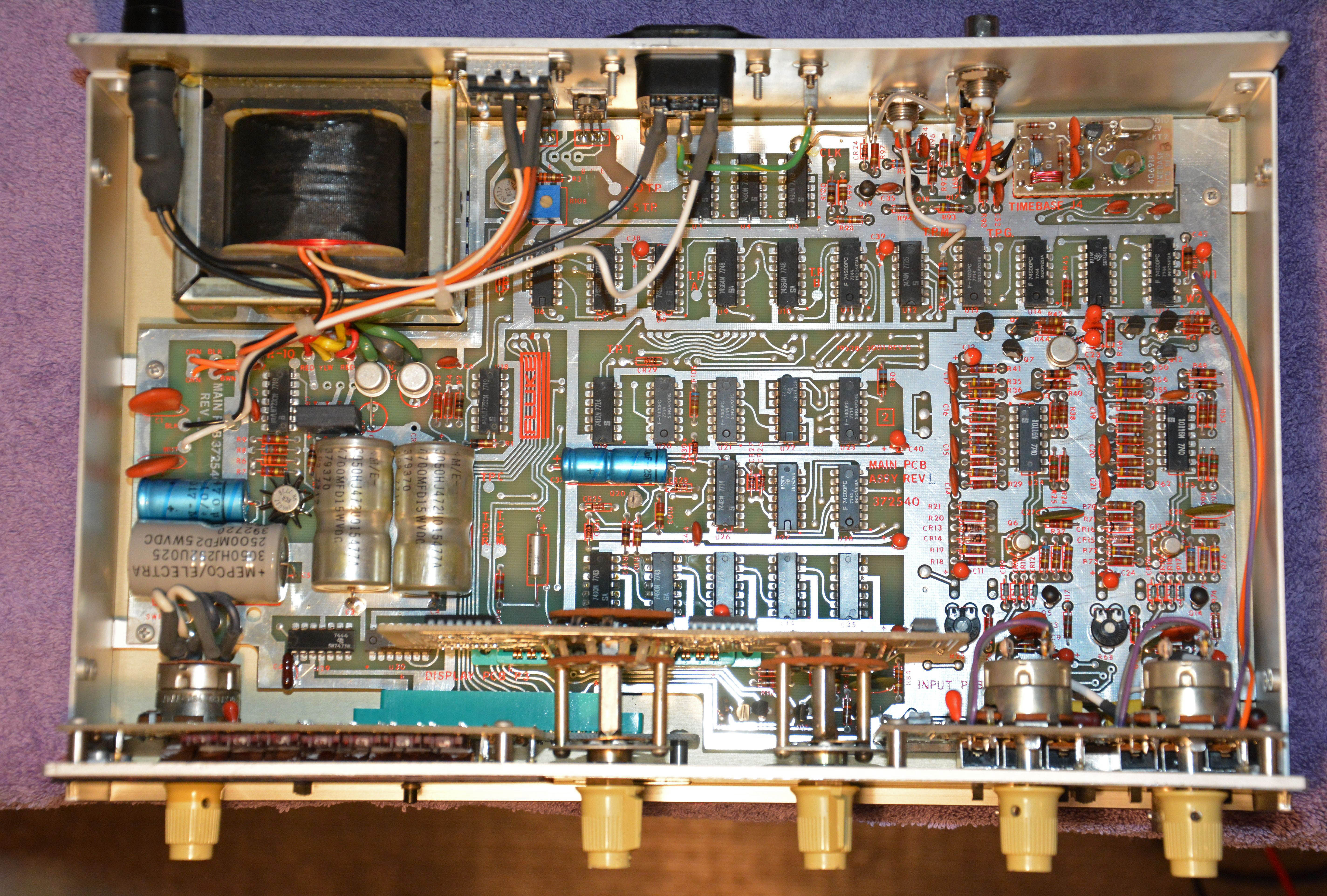
Besides replacing these capacitors, this unit needed some contact cleaning of the switches, potentiometers, and the display board socket, as well as bending the display LEDs to better match their masked holes in the face. It seems that the plastic display filter was installed slightly low at the factory, thus all of the LEDs had to be bent lower in order to line up with their holes, given that they were difficult to see at first. Overall, a very quick and easy job, and well worth it given the quality and usefulness of this device — like a power supply or oscilloscope, a frequency counter will never become functionally obsolete. Also, I should mention that I have the original instruction/service manual, and referred to it briefly during the job. As with nearly all test equipment manuals of the 70s and earlier, it is excellent. It is written in precise English, and with not a detail spared in explaining and presenting the circuits, thus providing the necessary information to keep the instrument functional indefinitely. Complete schematics (on foldout pages) and exploded views are included, as well as troubleshooting flowcharts. (Yet today, you're lucky to get even a block diagram, and forget about schematics!) My point is: a great deal of pride and care went into this manual, so I encourage all engineers reading to take note. I have scanned it and uploaded it here. HardwareThe 1952B is a typical piece of late-70s test gear. To show this, let's have a look inside. The top and bottom covers come off with four screws each, making it very easily serviced. Here's a view looking in with the top cover removed, prior to cap replacement:
A very clean design, with ample room to work. The bright red silkscreen and lack of a solder mask make the PCB especially striking in its appearance. Note the hand-routed PCB layout, with curves and odd angles. Note that all ICs are simple and common types still easily found today: 7400 series TTL chips, voltage regulators (the LM723s), and so on. Only the transformer, LED display modules, and some of the mechanical parts stand out to me as difficult to replace, but these are all unlikely to need replacement any time soon. Other interesting things:
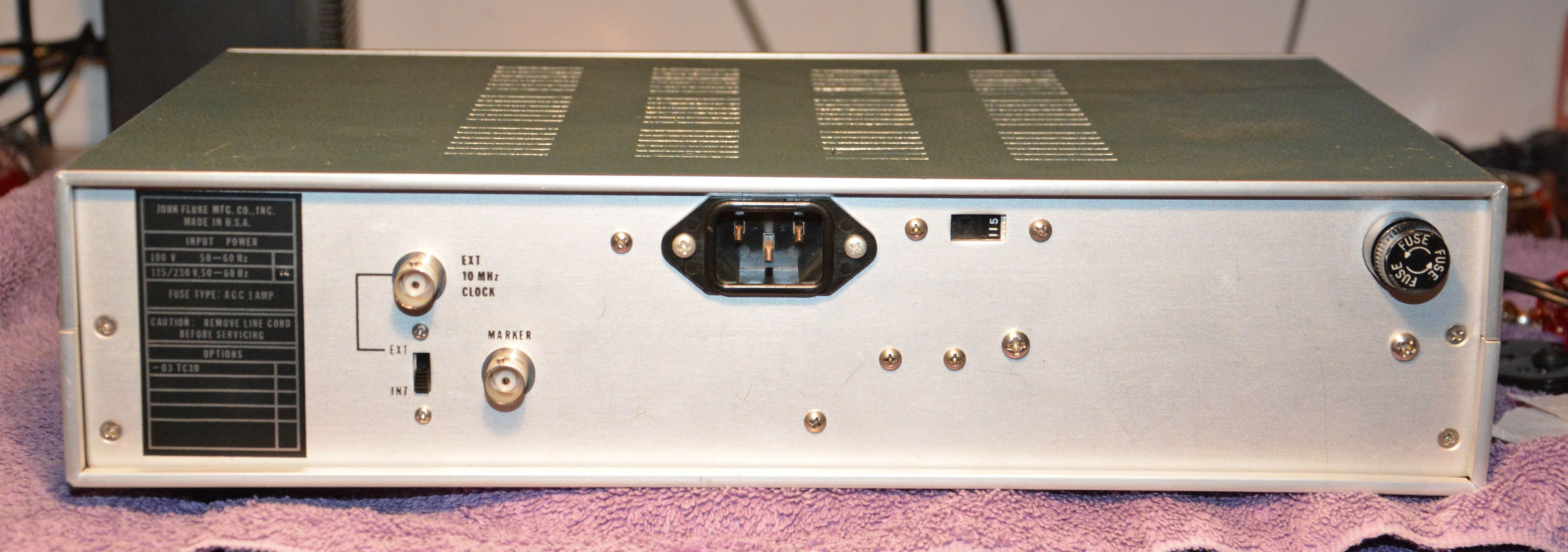
The frame and chassis parts, including the covers and the front & back panels, are aluminum. While the front and back panels are still nice and thick, the covers are relatively thin and with a plastic coating, so you can almost smell the transition to cheap plastic housings about to occur in the next series (1900A, 1920A, etc.) and in all of electronics in the 80s and beyond. In many ways, this was an "end of an era" device: the end of 99% generic non-programmable parts, the end of metal housings as the norm, the end of high serviceability (including great service manuals), and the almost complete end of American consumer electronics manufacturing. |
| If you notice any errors or have additional information that you would like to add, please contact me! |