Hewlett-Packard 5245M
Electronic Counter
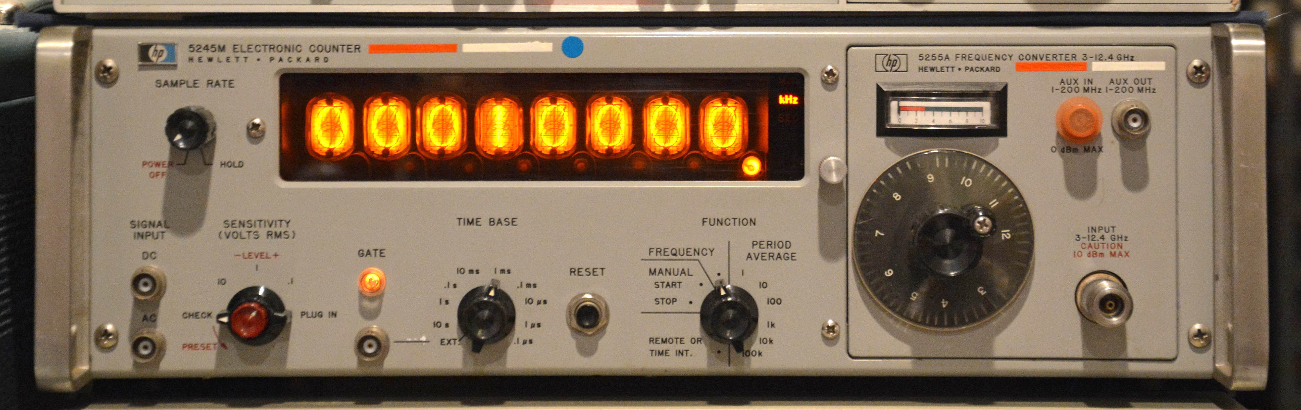
In summer of 2018, I repaired this beautiful HP 5245M "electronic counter" made in 1967. Not only is it a useful device, it is also a remarkable piece of engineering. The electronics are 99.9% discrete (with the 0.1% to be explained) and completely solid-state, using a mix of silicon and germanium semiconductors and their associated passive components. It is thus both highly serviceable and understandable at a fundamental level, since nothing is hidden away in complex surface-mount ICs, and there is no software. And of course, it has a gorgeous 8-digit Nixie tube display. It embodies everything I love about electronics, and so I hope to help and encourage others to use and preserve these instruments.
To give some background, the 5245M is a relatively early solid-state counter, predated by models such as the 5211, 5212 / 5232, and 5512 / 5532. It is a higher-stability version of the more common 5245L, which was an industry standard for years since its introduction in late 1962. The HP Memory Project gives 1968 as the 5245M's year of introduction, but I am not sure this is true, since despite what is noted, the Feb. 1968 journal does not mention the 5245M directly (just as the mainframe for the 5256A and 5257A modules). I suspect it was introduced closer to the 5245L's introduction. In any case, the 5245M uses a 5MHz oven-controlled crystal oscillator instead of 1MHz, and stability is better in every listed measure; for example, the aging rate (after warmup) for the 5245M is <5 parts in 1010 per 24 hrs, while for the 5245L it is <3 parts in 109 per 24 hrs.
This article coincides with two other counter articles: the Fluke 1952B Counter Timer and the Beckman 6148A EPUT and Timer. The Beckman article has a comparison between it and the 5245M—this is interesting since the Beckman is only three years younger, but is largely IC-based, and clearly took heavy influence from HP counters such at the 5245.
I will mostly skip discussing this counter's abilities and principles of operation, focusing instead on the repairs, as well as interesting hardware features not discussed elsewhere. Suffice it to say that it can count cycles, measure frequency or average period (of signals between 0 and 50 MHz), and display the ratio or multiplied ratio between two frequencies. If you want more info on the unit's operation, performance, troubleshooting, and schematics, they are presented in great detail in the service manual. While I haven't found this manual free online, a good indexed PDF scan is available from Artek Media. As well, a good scan of the 5245L manual is free online, which aside from the crytal oscillator circuits is virtually identical.
A brief mention should be made that my unit has the 5255A frequency converter module installed, which allows it to also measure signals from 3 to 12.4 GHz, spanning the entire C and X microwave bands, with the S and Ku bands partially covered.
Repairs
This was the simplest counter repair I've done so far, although it was at first unintuitive. The fault was that the counter measured frequency flawlessly when using the 0.1µs to 1ms time bases, but from 10ms up, it measured about 1.5 times too high (e.g. the 10MHz test signal showed about 15MHz), and was unstable in its reading. You might think that the decade divider circuit responsible for the 10ms time base had become faulty, since that would perfectly explain the issue. However, I used a scope to look at the time base BNC connector on the front (which outputs the chosen time base unless the switch is set to "EXT", in which case it becomes an input), and discovered that the time base signal on all interval settings looked bad, with a significant amount of 120Hz ripple superimposed.
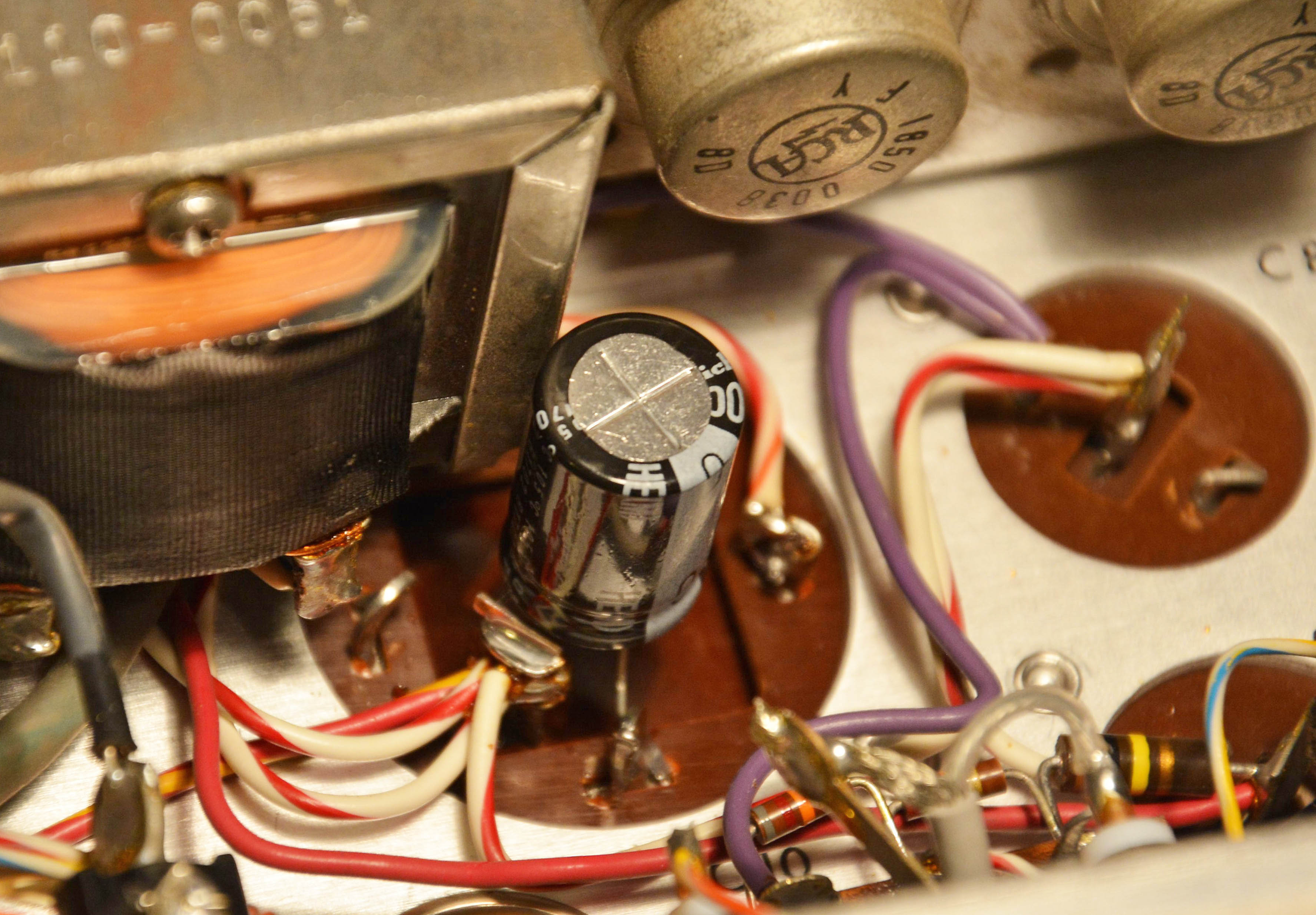
This suggested the very familiar problem of electrolytic capacitors going "open" (high-ESR / low-capacitance), especially the Sprague chassis-mounted can types used in HP test gear. As of this writing, I have seen a total of 5 Sprague cans fail in this exact way in HP gear. Sure enough, checking the can electrolytics, C10 (1500µF 15V) had unmeasurably high ESR, and the rest checked fine.
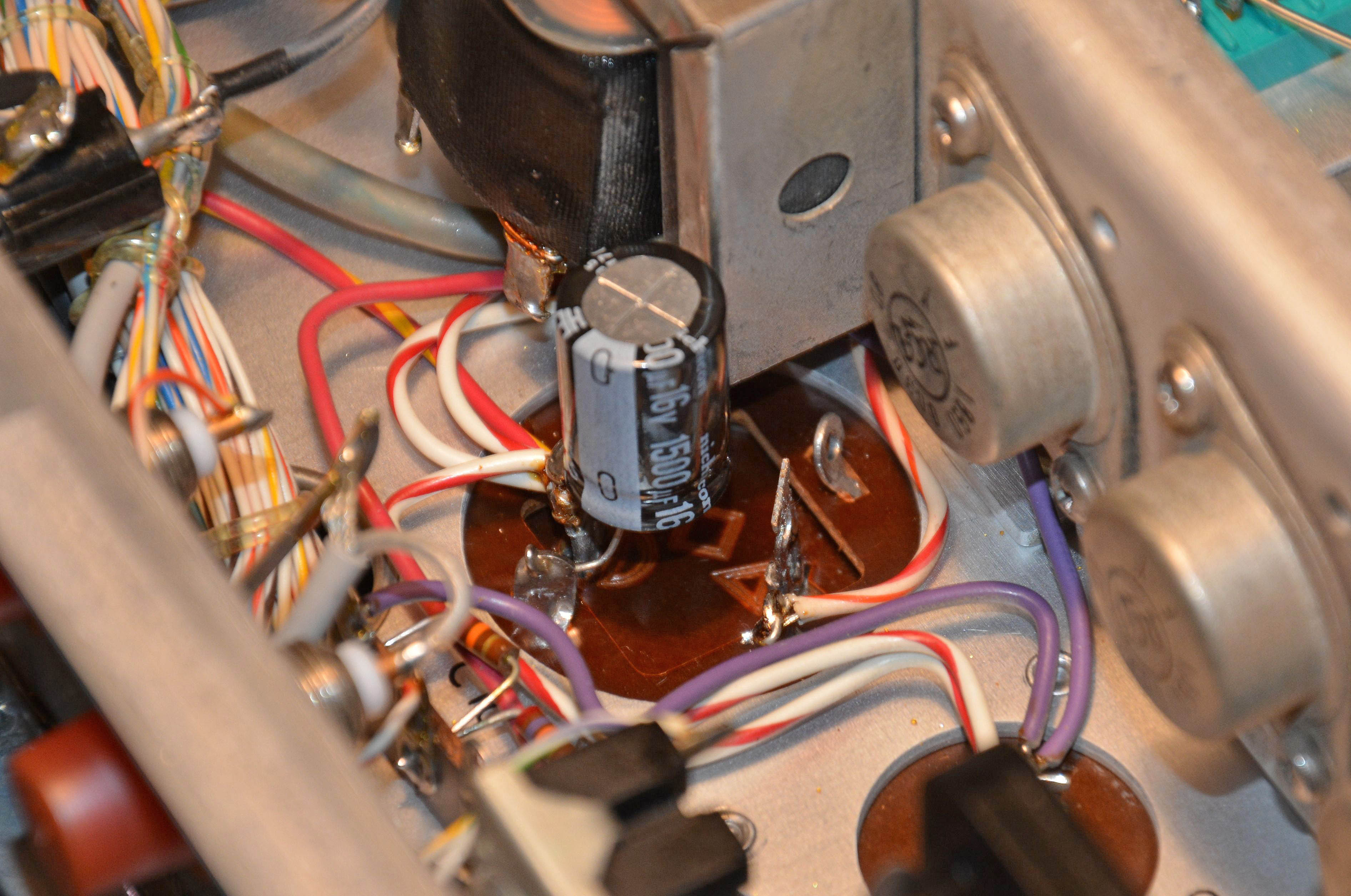
Since it is not possible to get a new physically identical replacement for this capacitor, I replaced it with a 1500µF 16V radial-leaded cap, Digi-Key part 493-1530-ND. This is a Nichicon UHE series part with a rated life of 10,000Hrs @ 105ºC: the best I could get. To mount it, I first desoldered the white-red-orange wire going to the negative terminal of the original capacitor and soldered it instead to one of the four can lugs (originally, the can was connected to the negative terminal with a small wire). Since the can on this kind of capacitor is insulated from both terminals, this disconnects the original capacitor while allowing it to remain physically in place. I then soldered the new capacitor between an unused can lug and the remaining positive terminal. If mechanical shock was a concern (such as if the unit was to be shipped), I would've added a bit of non-corrosive silicone to keep the capacitor in place, but as it is, the mounting is firm enough.
After this, the unit worked perfectly. Admittedly, I didn't check for perfect accuracy, given the lack of a precision frequency source; my check was simply comparing the readout to my other counters, which it matched. I did not even have to do any contact cleaning of the controls, since all were behaving properly from the start, despite that this instrument was sitting for years unused before I got it. Now that's quality: a 1960s instrument working fine after changing one part.
The question still remains though: why did it seem to work on the 1ms time base and below, but not 10ms and up? I think the answer lies in the period of 120Hz ripple: 8.3ms. Thus, over a time interval of 10ms and up, the input frequency is counted over at least one ripple cycle. Now, the time base signal was only affected for a small portion of the 8.3ms period: the portion where the faulty capacitor's voltage fell below the desired input voltage of its associated voltage regulator circuit. Let's say around 1/5 of the 8.3ms period was affected. So, for one, the chances of landing on a "good" section of the time base signal would be about 1/5. As well though, it may be the case that the shift in voltage (the ripple superimposed) over the counting inteval was causing the problem, so that even if one of the shorter sampling intervals "lands" in an affected spot of the time base, it would still count properly — this would explain why 1/5 of the counts did not seem bad.
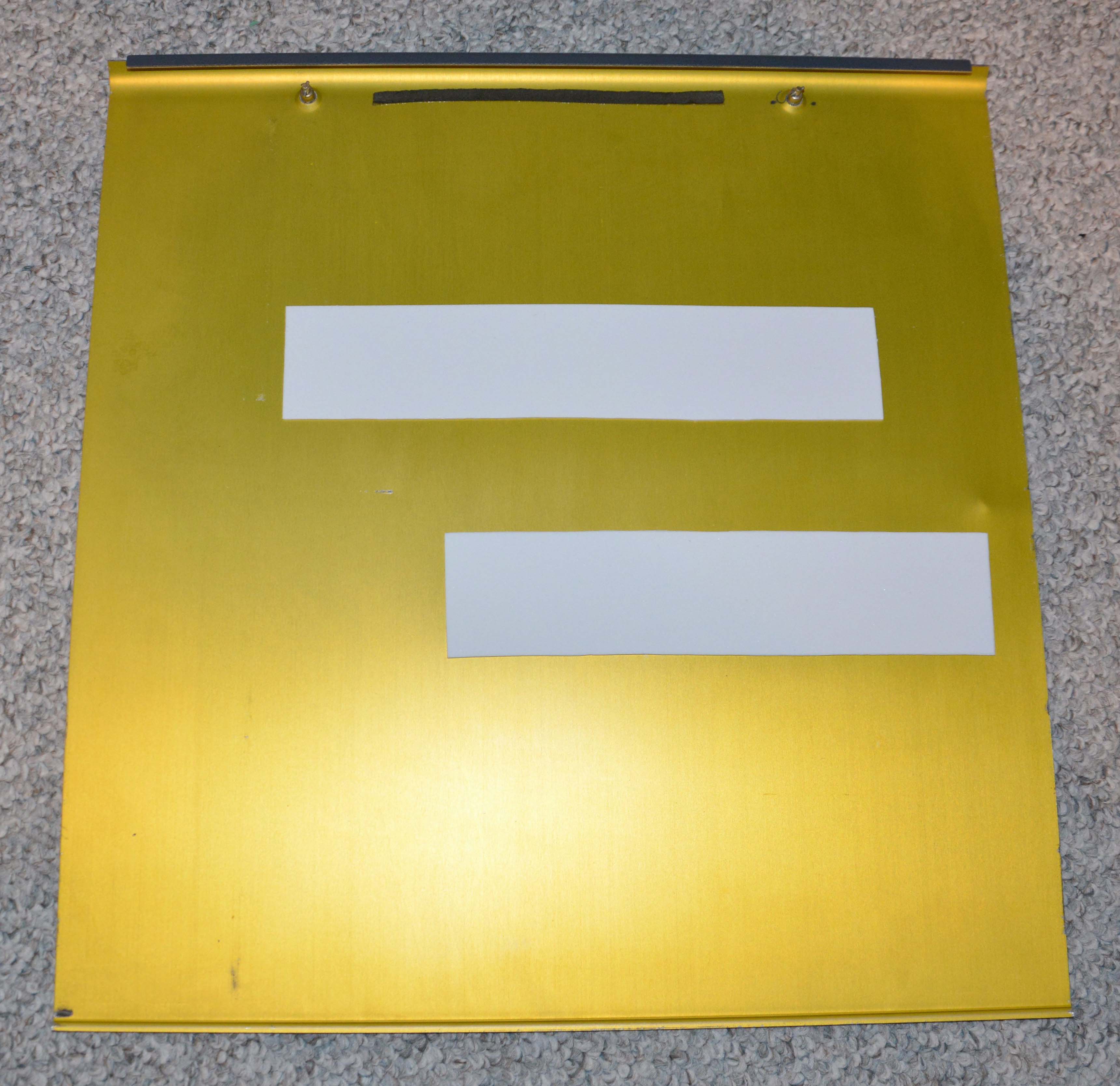
Lastly, although it wasn't strictly necessary, I replaced the decayed foam on the inner surface of the top and bottom covers. The original foam was easily removed by blowing it away with an air compressor, and the remaining glue (which was partially hardened, partially still sticky) was removed first with the edge of an old credit card (to remove the hardened parts), followed by paper towels soaked in acetone. Then new 2mm-thick EVA foam was applied. We will see how it holds up compared to the original foam. The finished top panel is shown below.
And of course, the usual dust removal (with a compressor and vacuum) and cosmetic cleaning of the knobs, panels, etc. was done.
Hardware
The 5245M uses 99.9% discrete circuitry, with hundreds of metal-can transistors and glass diodes, both in germanium and silicon types. (I will explain where the 0.1%, which may even be an exaggeration, comes from shortly.) Besides its continued usefulness, it is a beautiful piece of electronic history, showing fine workmanship and quality of both materials and design. There is no modern equivalent, due to the cheapening of everything that has occurred.
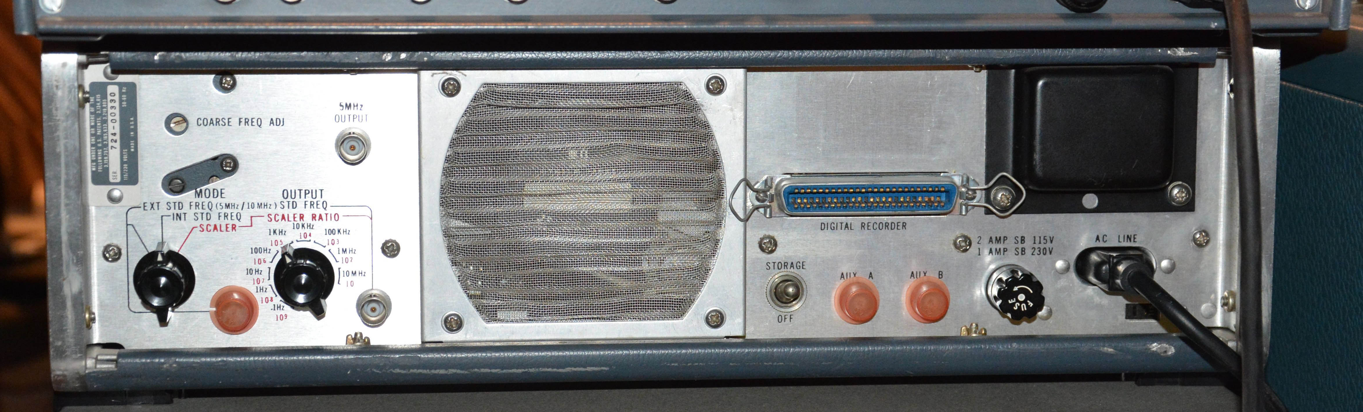
Before looking inside, have a look at the back. You can see the rotary selector for the time base source, choosing external, internal, or scaled internal time bases. Scaling is selected in decade steps by another rotary switch, and a scaled output is given. A fixed 5MHz output is also provided, which gives a sine wave of 1V RMS into 50Ω so long as the instrument is connected to power. This is because the oven and oscillator circuits are constantly powered, in order to keep the crystal always at operating temperature so that no warm-up time is necessary.
The "storage" switch selects whether or not the display shows the counting in progress, or just the latched result. The 50-pin "digital recorder" connector outputs data (normally encoded in 1224 BCD) to e.g. a Model 562A or 5050A printer / "digital recorder" unit, or a 580A or 581A digital-to-analog converter. All four of these devices are now extremely scarce — I could not find any examples for sale online, nor have I ever seen any in person.
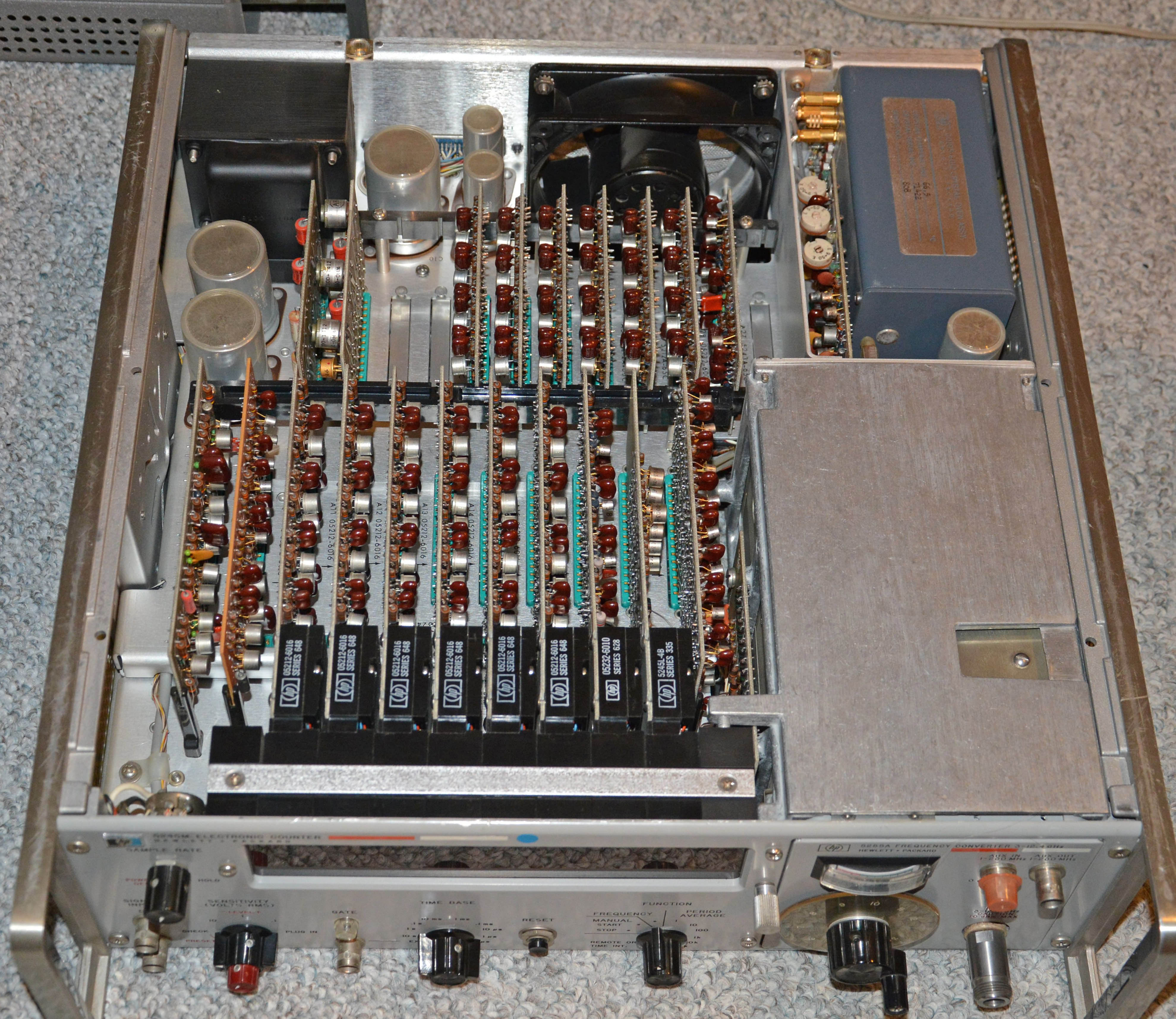
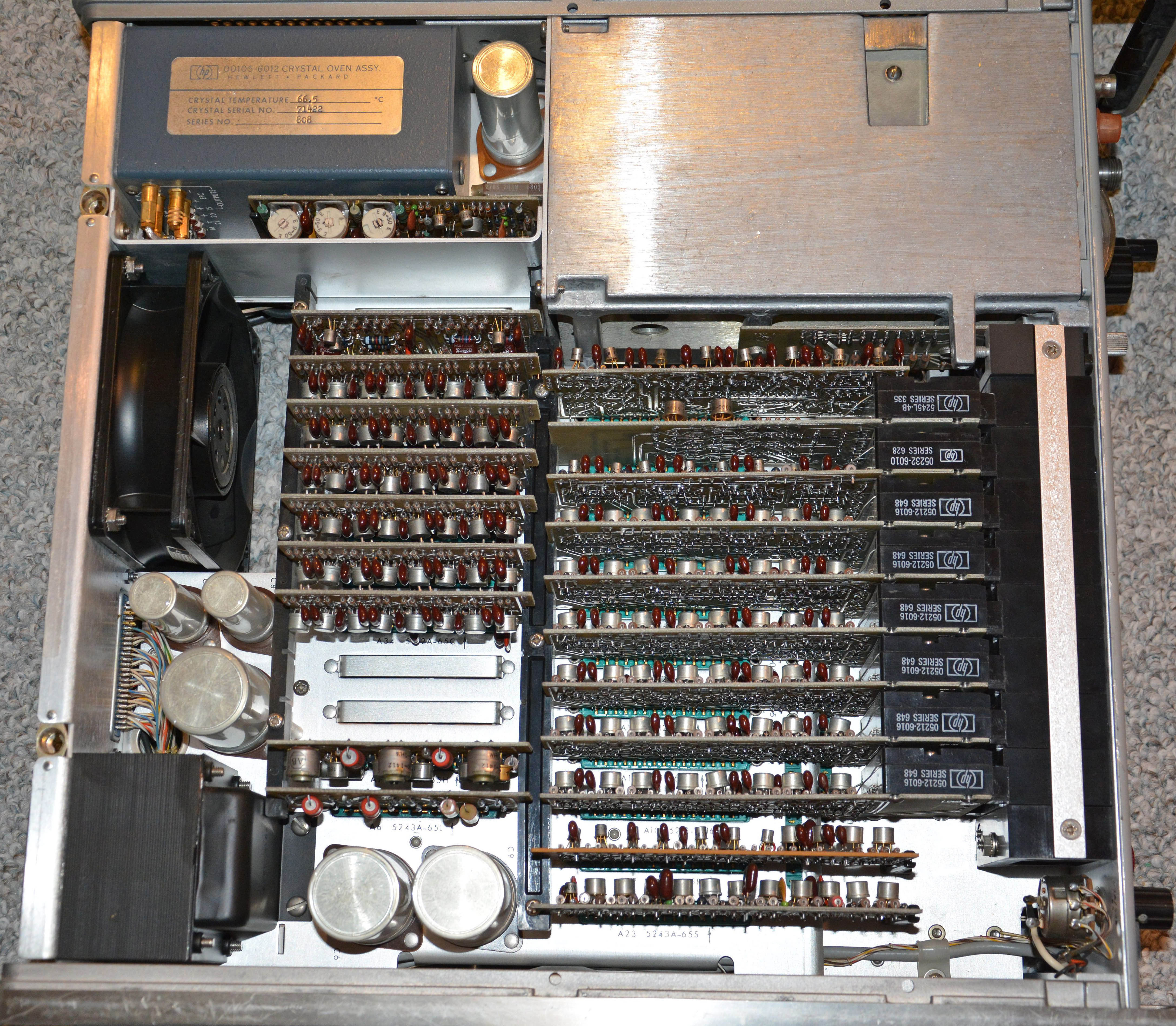
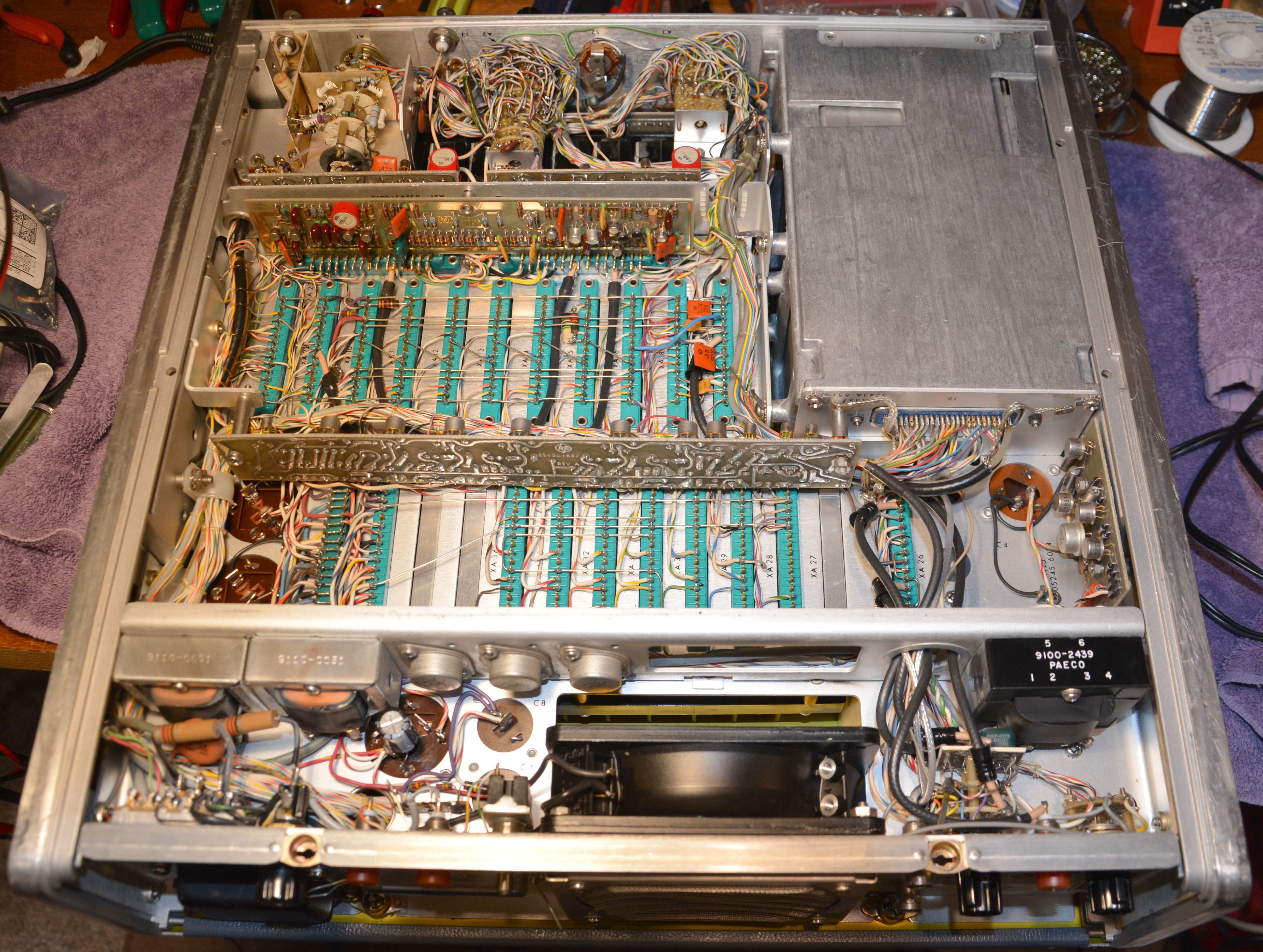
Removal of the top and bottom panels is easy, by means of two latches each (slotted for rotation by a large coin). Below shows two views looking in the top, followed by a view into the bottom. Note the 21 circuit boards mounted in a backplane arrangement, with the edge connectors mounted to the metal chassis and hand-wired. Every board except one has epoxy-fibreglass substrate; only the gate control board (A22 in the SM) is phenolic paper.
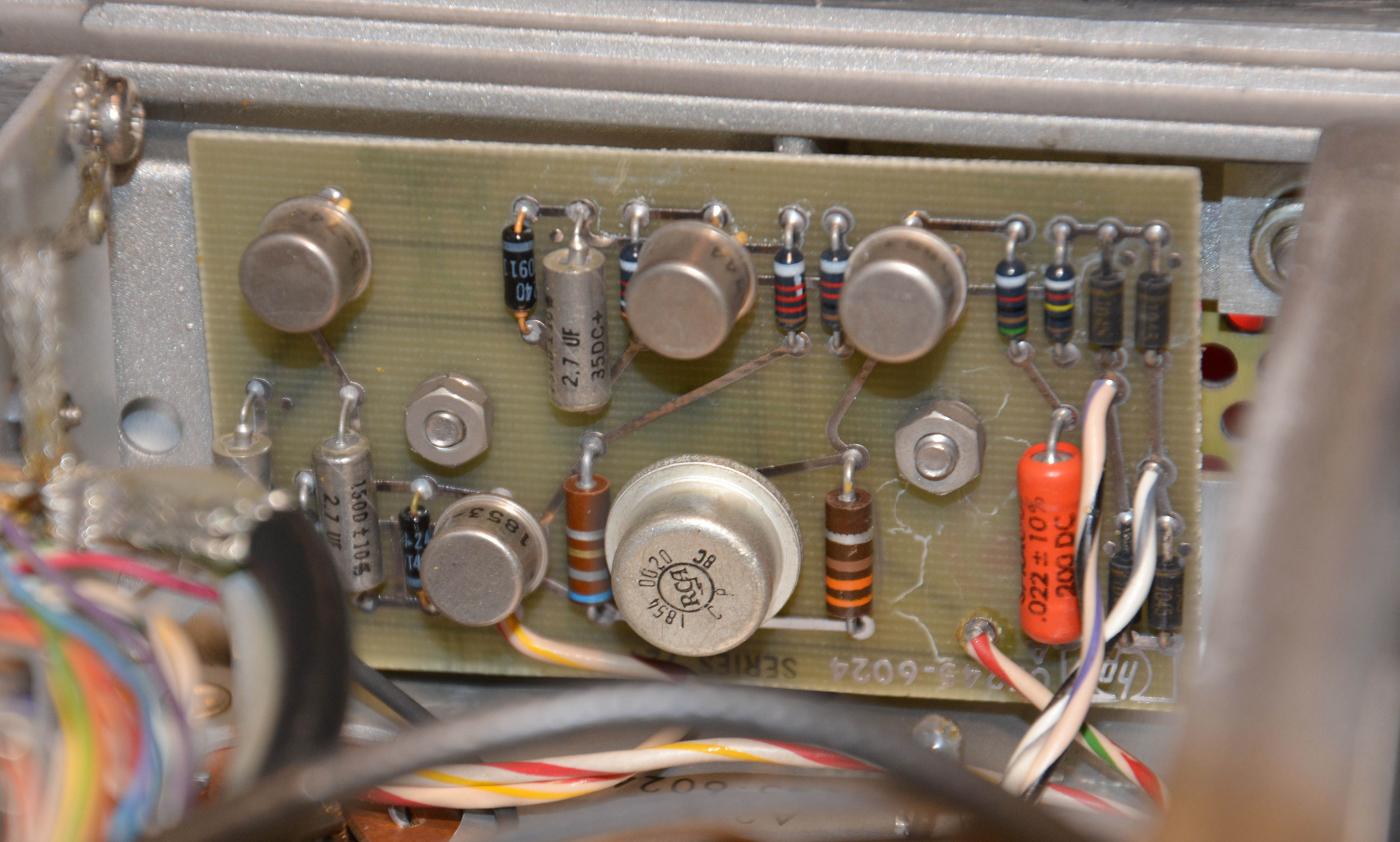
Let's look at a few boards more closely. Below is the 05245-6024 oscillator power supply, assembly A25 in the service manual. It's the simplest board, containing just a current-limited linear regulator; the big RCA 1854-0020 is the series pass transistor. Note the component quality: metal-can transistors with gold-plated leads, a glass diode with gold-plated leads, solid axial tantalum capacitors (which I have never seen fail—not that it's impossible, but they seem better than wet aluminum electrolytics), and a Sprague orange axial film cap as well, which is probably type 192P made with polyester film and aluminum foil (not metallized). As with the rest of the unit, the resistors are a mix of Allen-Bradley carbon composition types, and another kind that is probably carbon film.
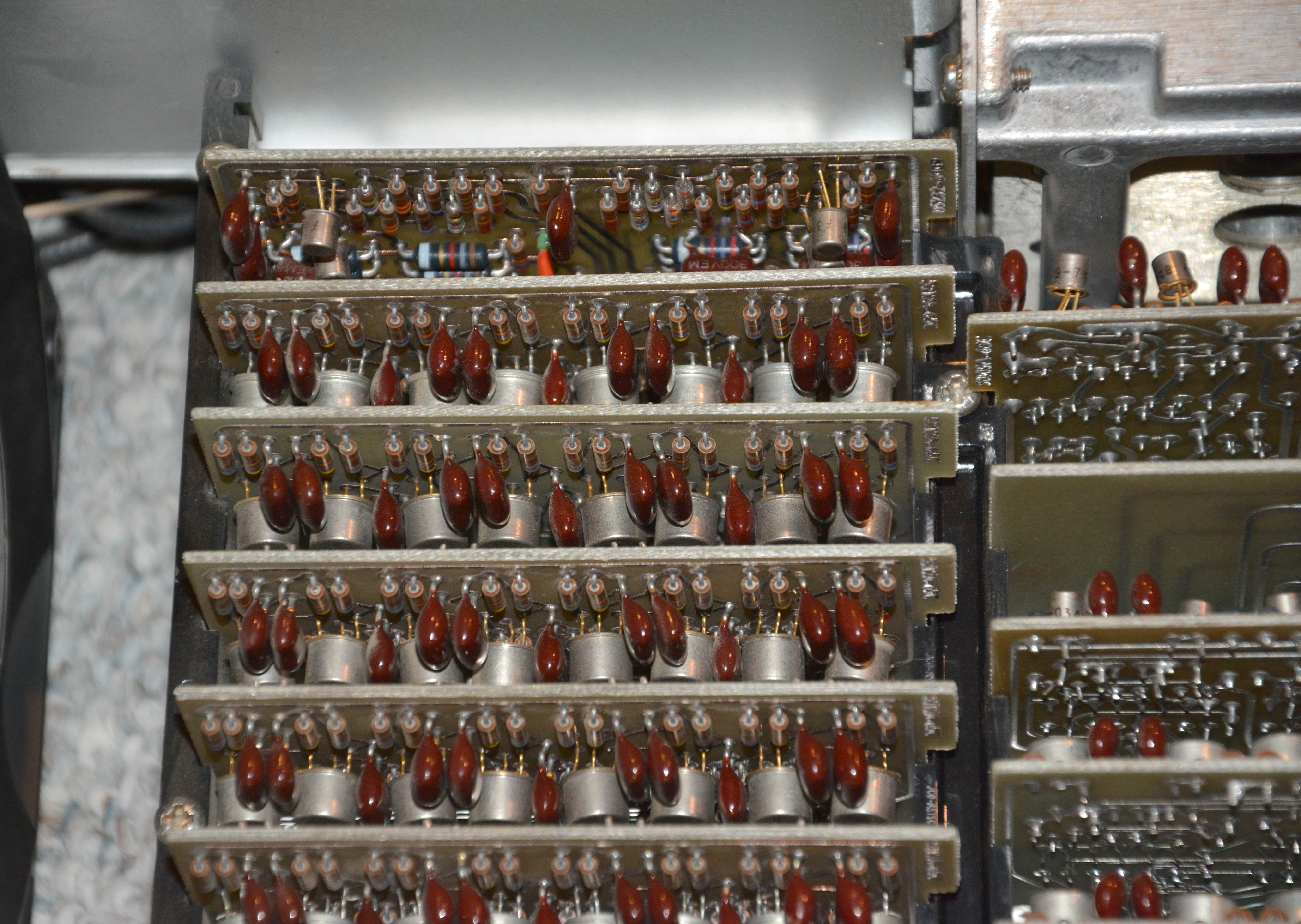
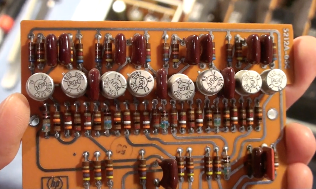
The left image below shows mostly the decade divider boards (assemblies A28—A34). Each board contains four bistable multivibrator (i.e. flip-flop) circuits, arranged to produce one output cycle for every 10 input cycles. Seven are connected in a dividing chain, starting with a 1MHz signal from the A26 multiplier / divider assembly, thus giving the time base signals in decade steps down to 0.1Hz. Note that A28 is a unique "5MHz divider" (whose input is actually 1MHz), part number 05232-6009, while the rest are 600kHz dividers, part 5212A-65C. The latter, you may correctly assume based on the prefix, are identical to the decade dividers of the 5212A / 5512A and 5232A / 5532A electronic counters. The right image shows one of the same boards from my 5532A made in 1966—it is identical besides the phenolic paper subtrate instead of epoxy fibreglass.
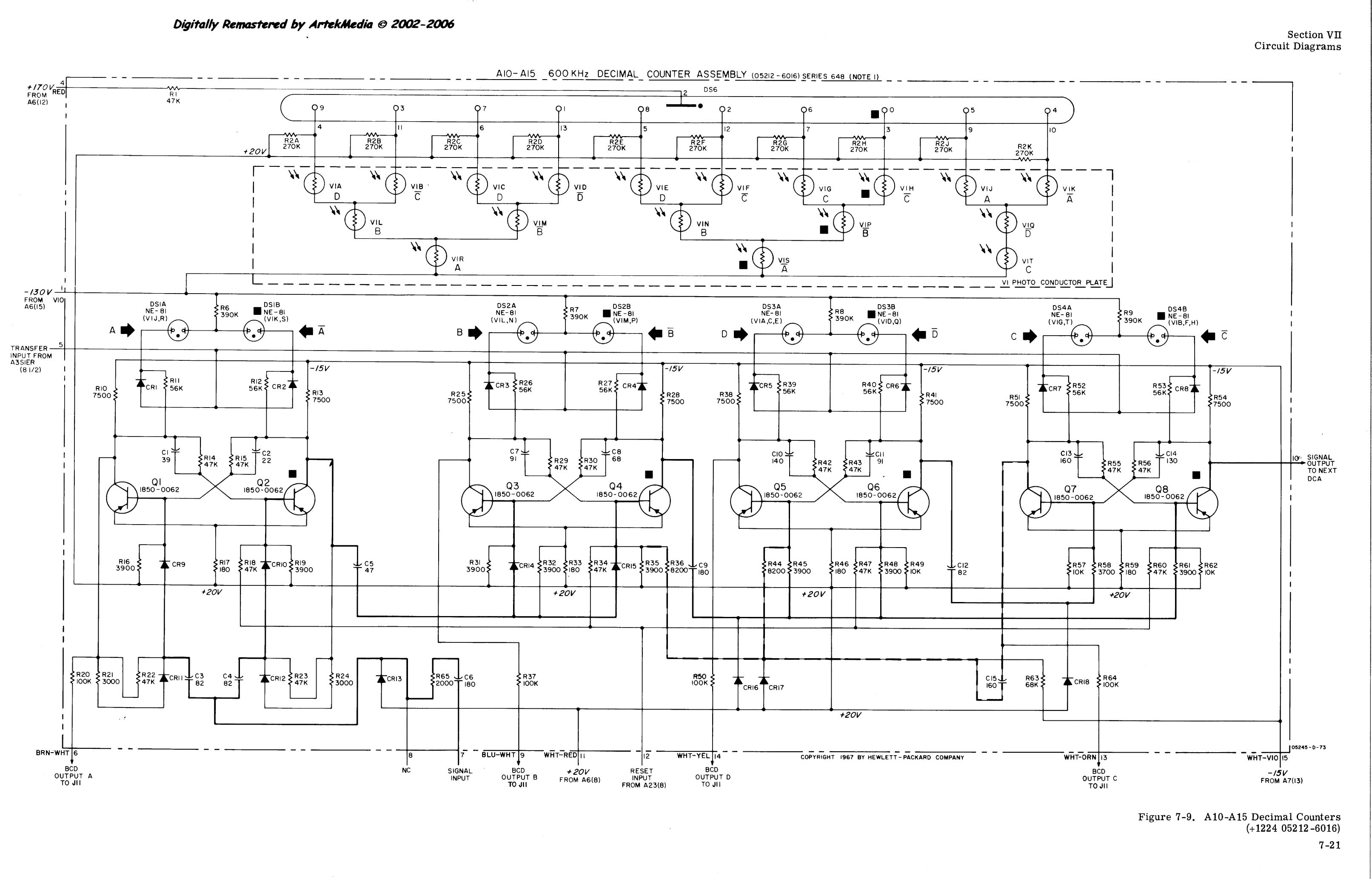
Below shows a not-so-good view of the decimal counter boards, which are count and display the number of cycles (of either the selected time base or period/divided period signal) for the length of the gate pulse. These are mostly part 05212-6016, and have more or less the same kind of flip-flop BCD counter arrangement as the decade divider boards, except with an associated display. Decoding the counter's BCD output into decimal control lines for the nixie tubes is done in a very interesting way, using an array of neon lamps and photoresistors housed in the black boxes towards the front. Have a look at the schematic from the Artek SM to the right. These black boxes can be disassembled, and while the neon lamps are discrete, the photoresistors are all integrated on a "thick-film" technology, and R2 is an integrated array of 10 resistors. This is why I say the electronics are 99.9% discrete. Luckily, it seems the photoresistors hold up well, and while the neons do age, and they can be replaced with common lamps such as the NE-2—see this forum thread, which also has a great view of the assembly when open. There is also a good diagram and explanation of the decoder here.

I forgot to take pictures of them, but on each of the input boards, there are also two parts that are not quite discrete: the 1854-0249 dual NPN transistor, and the 1855-0047 dual n-channel JFET. They are both just two transistors in one package, so even if they became unavailable, you could just match two similar discrete transistors to make a pair, and attach them together for thermal coupling. The 0047 is still available from Sphere Research Corp., which also has plenty of other original HP transistors.
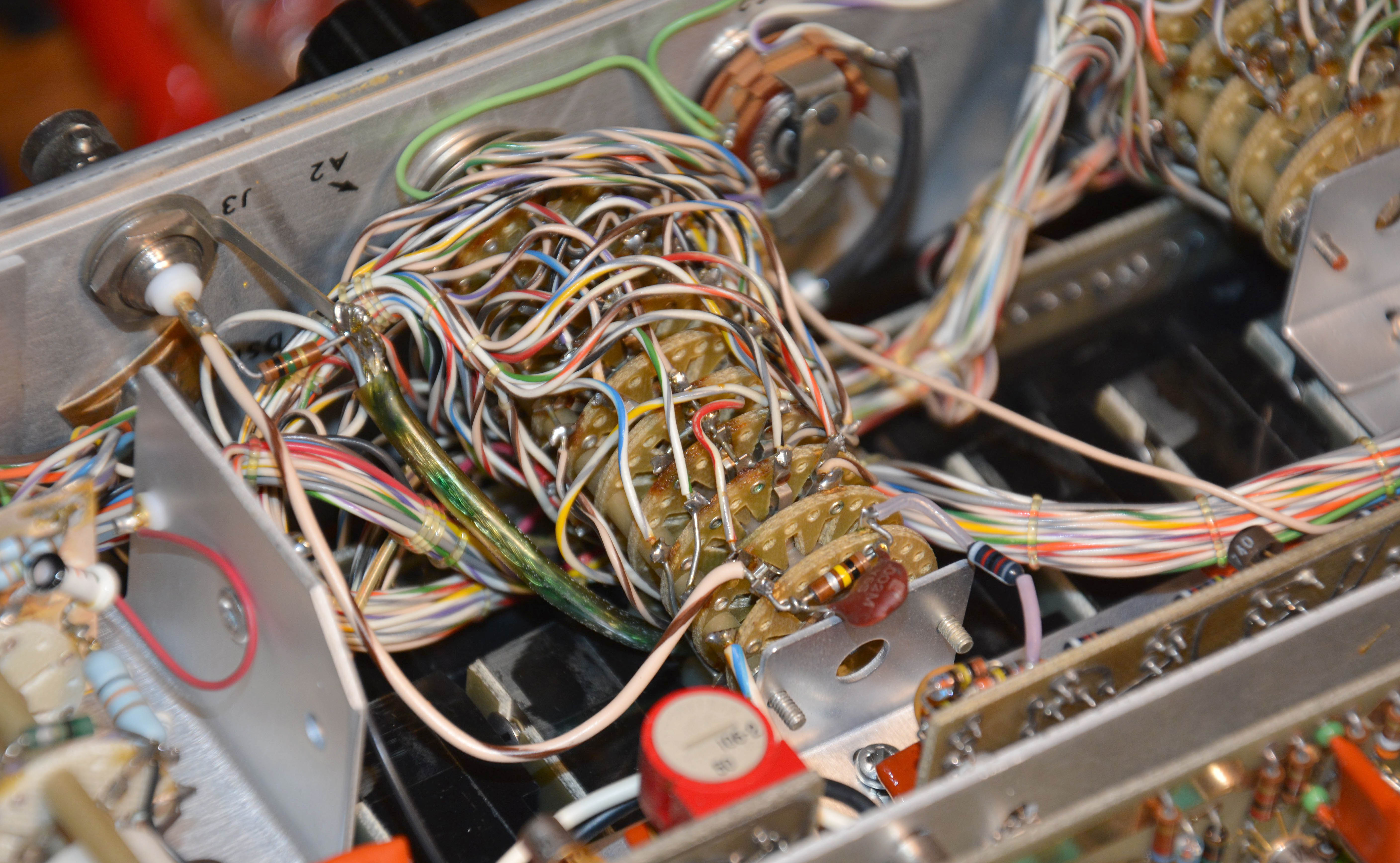
Lastly, have a look at the wiring of the function switch. All of this was done by hand. Note the cable lacing using plastic string, which became very common in Japanese equipment in the years to follow.
Links
Sphere Research Corp. — Source of many types of transistors for HP equipment.
HP 5245L manual on Kenneth Kuhn's website — Different crystal oscillator, but otherwise nearly identical to the 5245M. The true 5245M manual can be found from Artek Media or other eBay sellers.
HP Memory Project Collection – Time & Freq. — Collection of frequency / time measurement equipment, giving a timeline of classic HP counters and their modules & accessories.
Antique Radio Forums – HP Nixie Tube Decade Counter Board — Info on repairing the neon lamp/photocell decoder section, including a good picture of the inside.
Decode Systems – Nixie Displays — Good info on the 05212-6016 Nixie display modules, including a description of the decoder circuit.