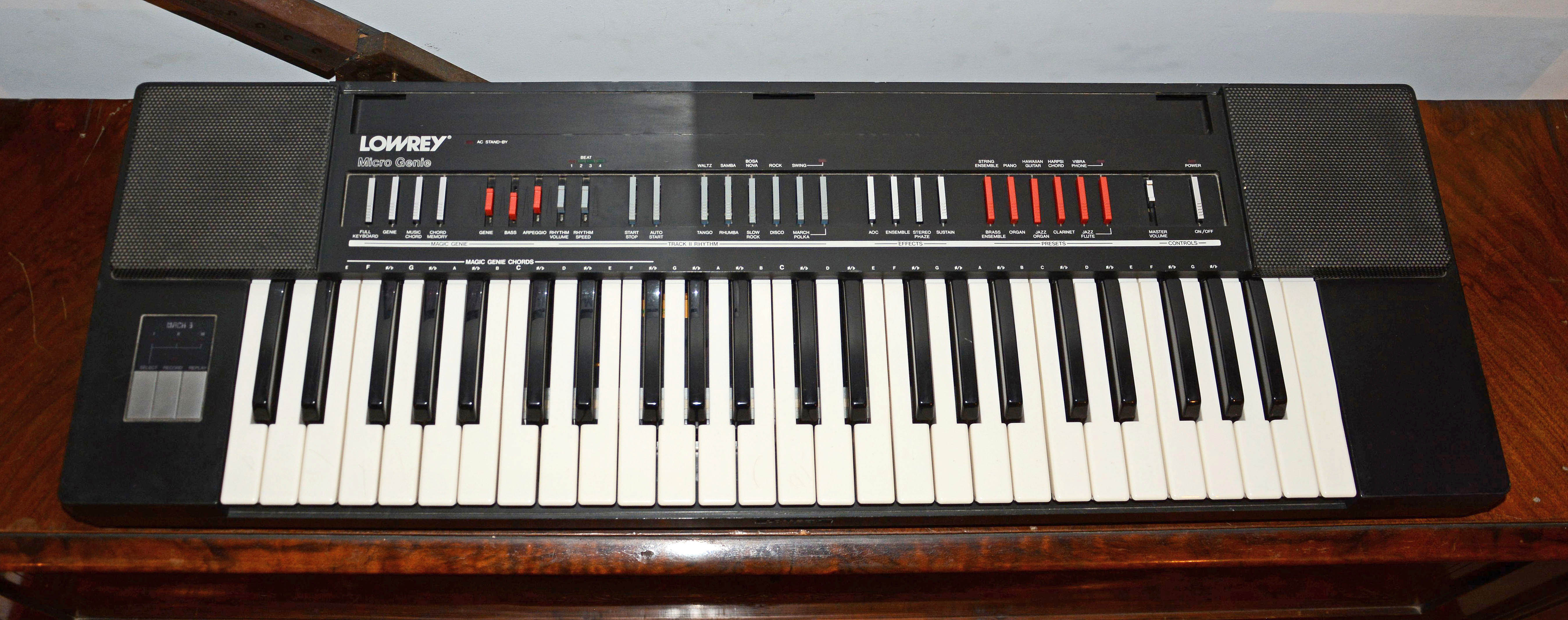
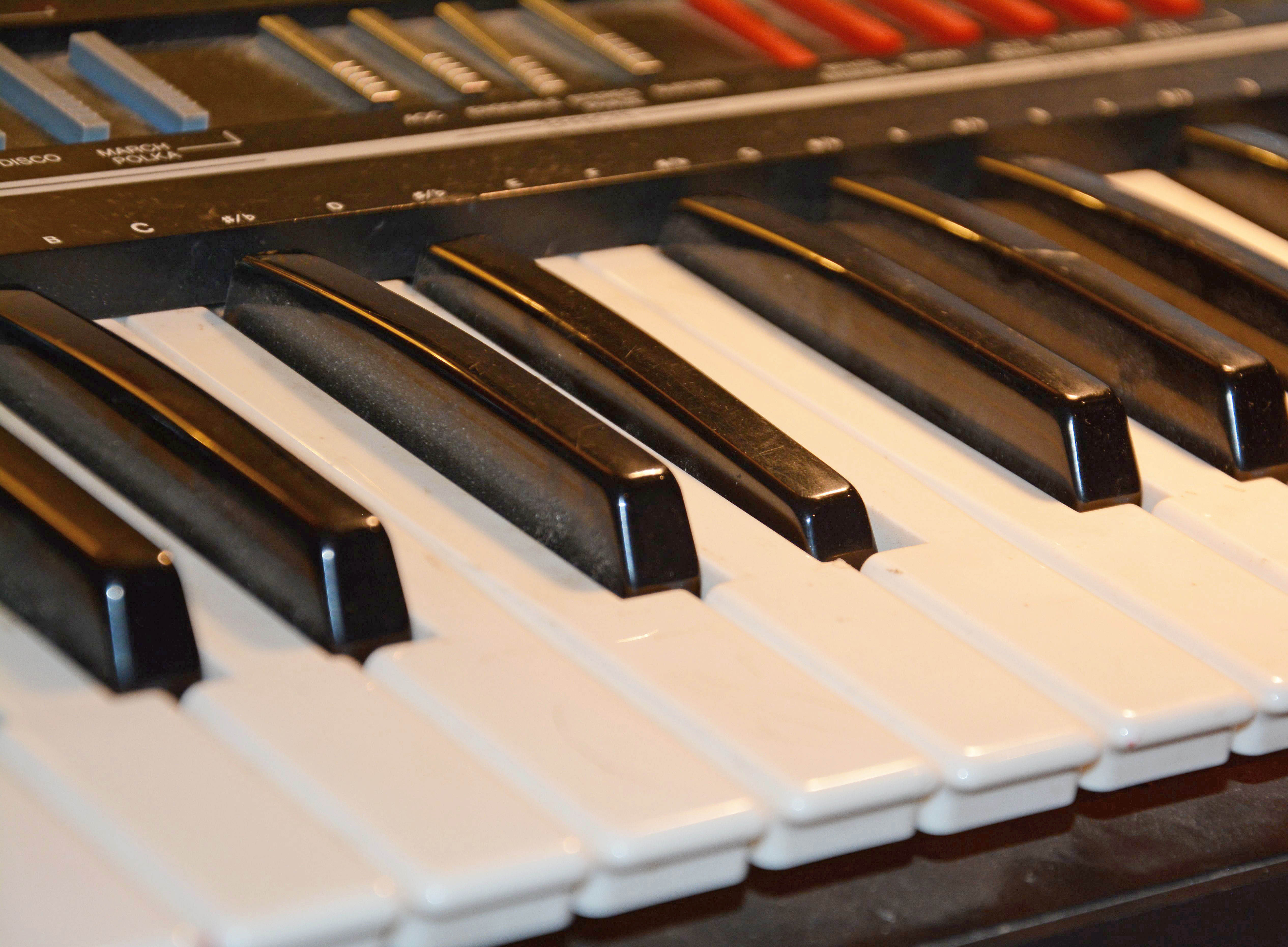
Lowrey Micro Genie V-100Portable Keyboard / Polyphonic Preset Synth
This article was originally published on my old website "JCS" in simpler form back in 2015. It was massively revised and re-published here in 2019, and additional large revisions were done in 2021 following my acquisition and writeup of two Lowrey vacuum-tube organs (the "Holiday" LS and "Festival" FL), which I consider much better instruments both in build quality and musical capability. I sold my V-100 in early 2020 for $50.00 CAD, and haven't regretted the decision. The Lowrey V-100 was introduced in 1982 as part of the "Micro Genie" line of inexpensive portable home-entertainment keyboards. Lowrey, an American company that saw great success in the electronic organ field starting in the mid '50s, was by the late '70s suffering from stiff Japanese competition. Such firms were not only directly undercutting Lowrey when it came to home organs, but were also diverting away the home-entertainment buyers with new things like "portable keyboards" and "home synthesizers". These new instruments from the likes of Yamaha and Casio were loaded with imitative presets, auto-chords, auto-bass, drum machines, and other easy-play functions that were common in home organs as of the '70s, yet they were much lower in cost and bulk. Lowrey saw the writing on the wall and decided to cash in on Japanese success while they could by re-branding some such products as their own. Yes, the V-100 is not really a Lowrey product. Rather, it was made by the Victor Company of Japan (i.e. JVC), and is a rebranded version of their KB-500 model with only slight modifications. Cosmetic differences include changes to the text wording—e.g. the "Mach 3" sequencer section was originally called "Compucorder"—and as well, some plastics are different colors, e.g. the black side panels on top are white on the KB-500. Functionally speaking, there might be a difference in the way the accompaniment recognizes chord fingerings, but I've only read this. I don't know of any other differences. In addition to the V-100, Lowrey marketed at least eight other models modified from JVC KB-series instruments; see here for a list. I imagine Lowrey picked this series to rebrand because JVC never marketed them in North America. Lowrey was bought out by the Japanese company Kawai in 1988, at which point they shifted focus from cheap home-entertainment instruments to big-ticket ones, with rich seniors as their target demographic. As well, note that Lowrey called the V-100 a "portable organ"—naturally, given their history. However, these Micro-Genie keyboards can hardly be considered organs at all, mainly because they use preset voices not intended for combination (though it is sort-of possible by releasing preset buttons simultaneously). All real organs except the most modest reed types have the ability to combine multiple tone colors in multiple pitch registers. Yet, the V-100 has no stop tabs or drawbars, nor any couplers or pitch register controls. Not even a vibrato control! There are just two "organ" presets, neither of which are exciting. All other presets are percussive or otherwise not organesque. Its 49-key "manual" does not even cover the same range as the average spinet (i.e. 56 notes), nor is there a pedalboard. More accurately, the V-100 is a polyphonic preset-based synthesizer with rhythm and auto-accompaniment features. There are 10 presets selectable by pop-out buttons. Synthesis is digitally-controlled "semi-analog": generation of the basic pitched tones is done by a custom "programmable tone synthesizer" chip (which uses both analog and digital circuitry, as will be explained) under the guidance of a microcontroller. External analog circuitry filters and shapes these basic signals into the various preset voices, as well as the music-chord/Genie, arpeggio, and bass signals. As well, there are analog drum sound generator circuits (made with simple op-amps, gates, and discrete transistors), which are triggered by the same microcontroller system that controls the synth chip. More on all this in the "Hardware" section below. Since it was not available online, I purchased a copy of the service manual on eBay and scanned it, and it can be downloaded in full quality here, or in compressed form here. This manual is relatively detailed and well-written, giving descriptions of every circuit, a block diagram, and complete well-drawn schematics. Features
Trivialities
RepairsThis instrument took some time to fix, due to its poor physical condition, and the use of a notoriously bad type of electrolytic capacitors. Every fault was basically mechanical. To give some background, this V-100 was picked up in April 2015 at Lazaro's Music (which was the best shop in Edmonton for vintage equipment), where it had been stored almost inaccessible among a pile of other things. I had passed it over at least three times before, thinking it was another unexciting modern cheap plastic digital unit. One day I looked at it more carefully, and realized it was a not-that-modern cheap plastic semi-analog unit—more exciting, at least! After testing it and noting multiple problems, I negotiated a reasonable price, and took it home on the city bus. Nobody seemed to notice. The initial problems were:
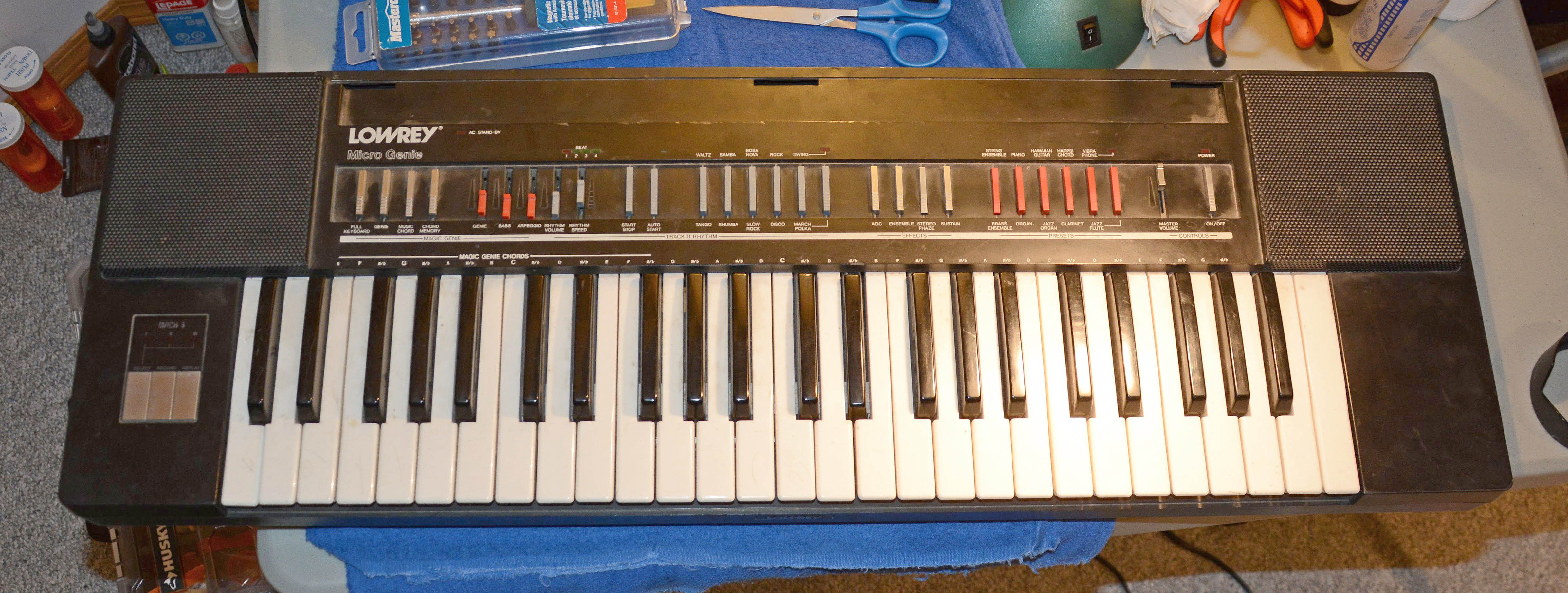
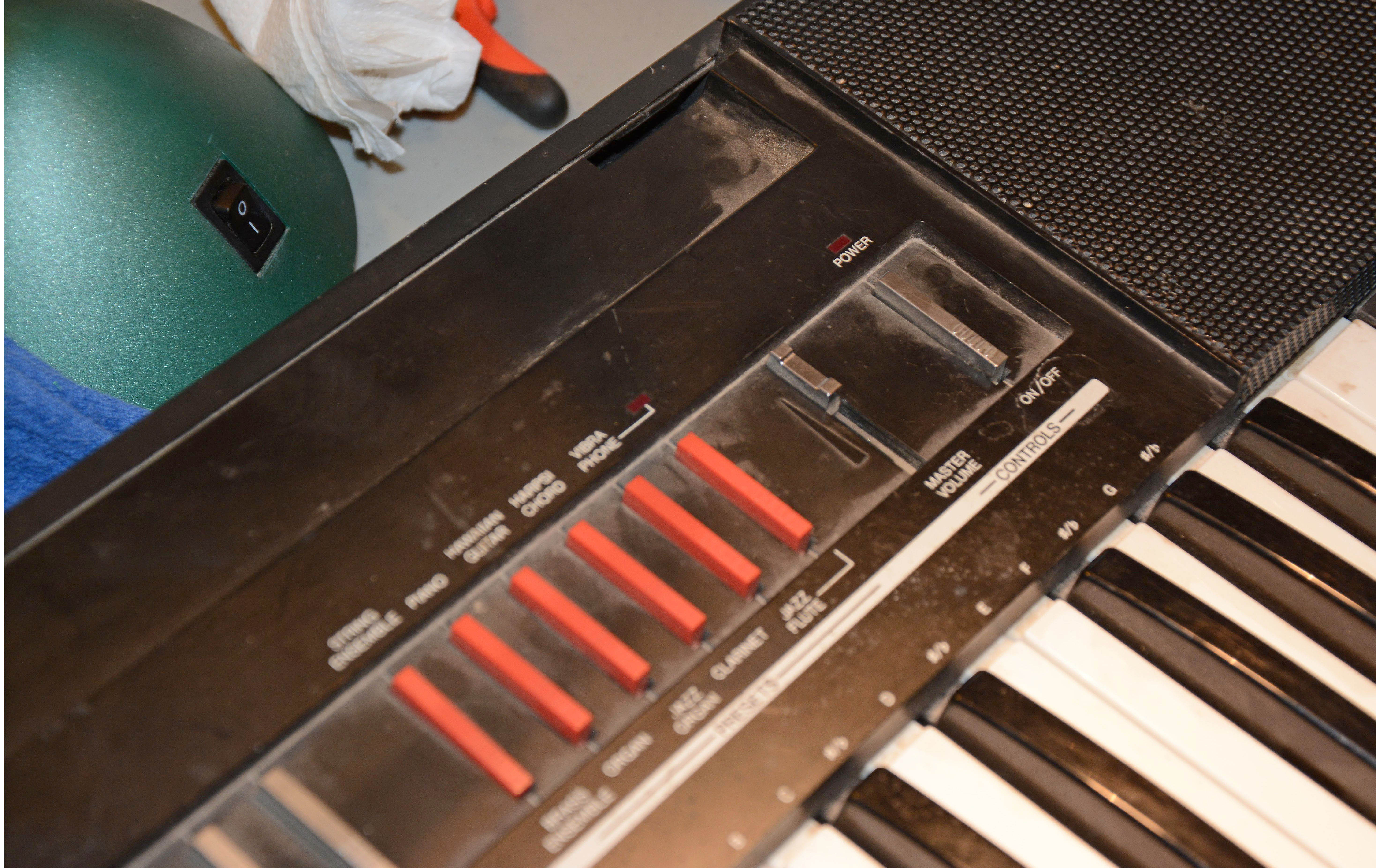
As well, the original stand was missing, which would have attached to the eight threaded mounting points in the bottom. Two other parts were also missing: the transparent plastic music stand / dust cover, and the battery cover. Here are pictures of the instrument pre-repair:
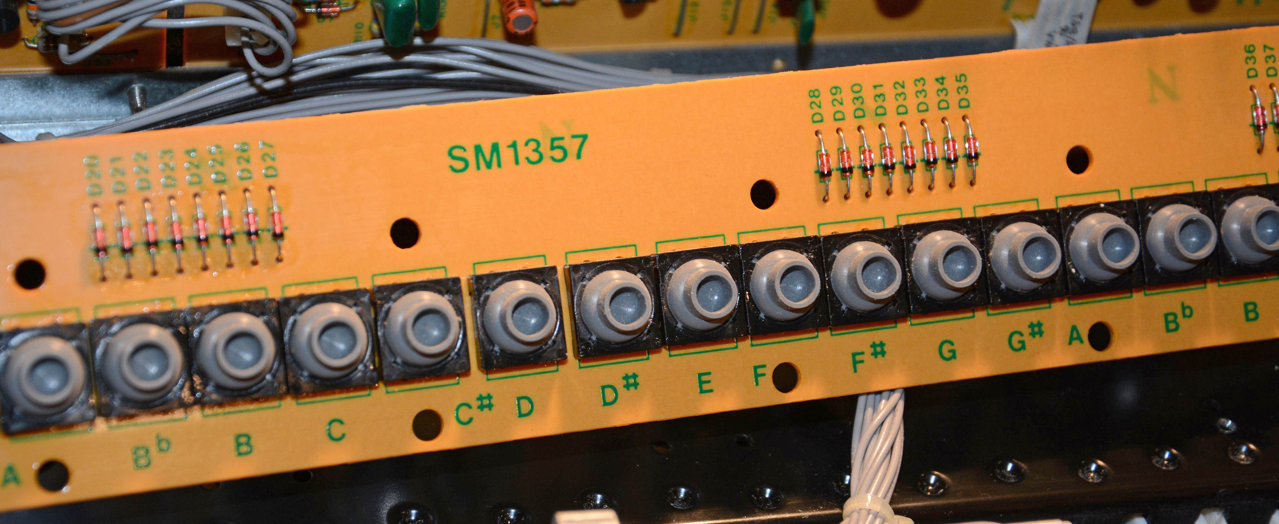
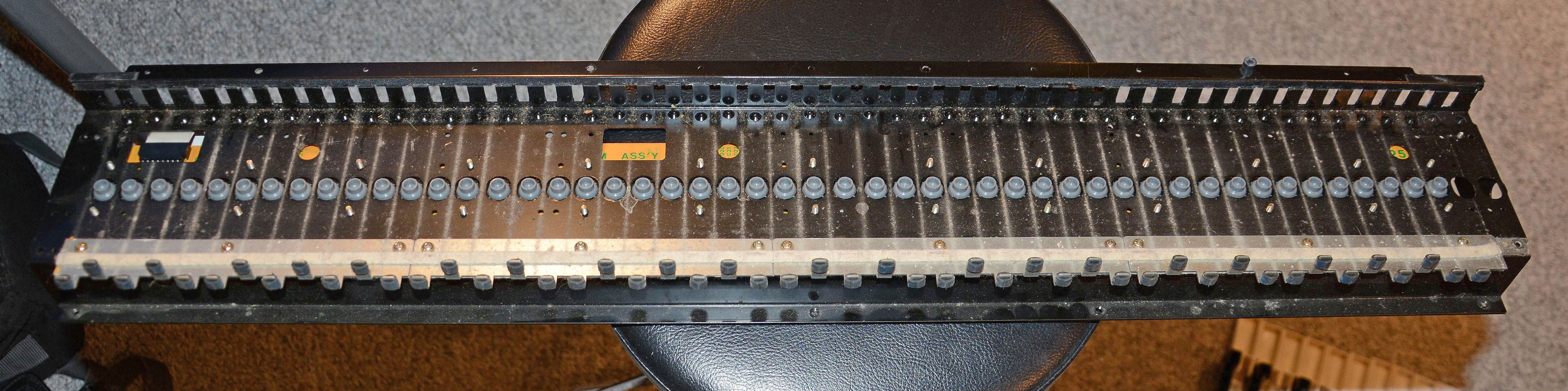
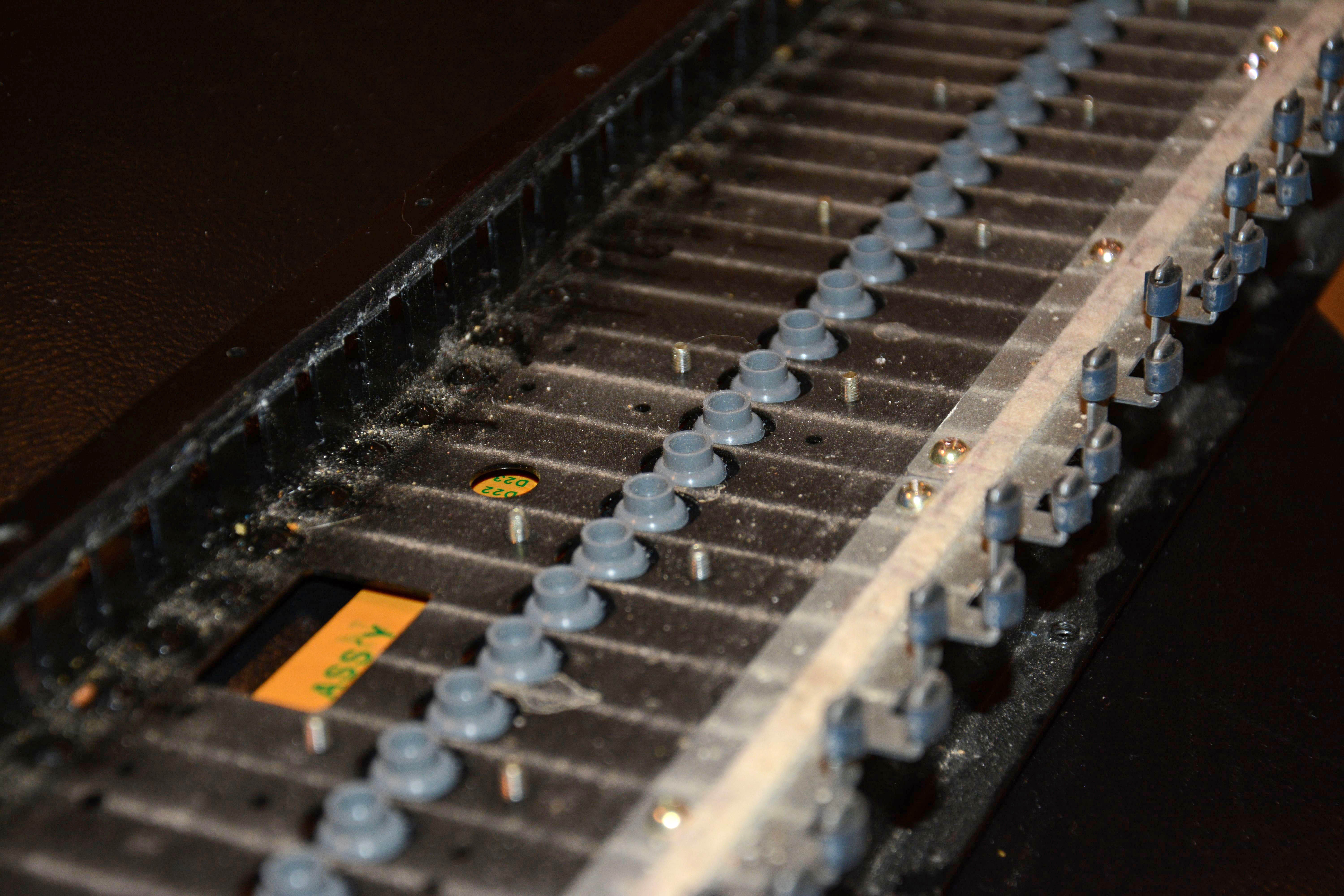
The first things repaired were the non-sounding keys, all caused by dirty keyswitch contacts. I started by dissassembling the instrument to the point of removing the keyswitch board, called the "MKM Ass'y." It is an unusual design of the transitional '80s: a rubber dome-switch keyboard where each switch is a discrete component, similar to a 12 x 12 mm tactile switch. This was a surprise, since dome-switch keyboards usually use one or two large boards with contacts printed directly onto them, and rubber/silicone membranes with many integrated domes. Of course, this makes the parts more specialized, resulting in poorer parts availability, and the integration means that if one section fails, then the whole thing may require replacement. So, although I appreciate the discrete dome switches because they are individually replaceable, I have not found a source of replacements. And indeed, I did not have to replace any, since they were cleanable. While the contacts cannot be directly wiped, they can be "indirectly" cleaned by applying spray contact cleaner to every switch along the edges of the domes, so that it seeps onto the contacts inside, and then massaging the domes for about a minute each. With four fingers, four can be massaged at a time. This process fixed all but one especially dirty switch, which I had to re-clean and re-massage. I should also mention that when I did this back in 2015, MG Chemicals' Contact Cleaner with Silicone was used, but today I would instead use MG Chemicals Electrosolve, which is nearly the same except without silicone. All keys still worked perfectly as of February 2020 when the keyboard was sold.
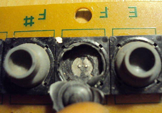
A fellow in Ukraine known as T-150 (who also provided the tone generator chip datasheet for the Kawai KMA-37) sent me the photo below, showing the inside of a dome switch. It appears that the dome itself has a carbon-infused disc as expected, but the fixed contacts are small metal dimples, rather than the usual printed carbon traces. This probably explains why the switches age the way they do; the metal contact surface oxidizes, whereas the usual carbon contacts do not oxidize, though they can become contaminated, causing similar issues.
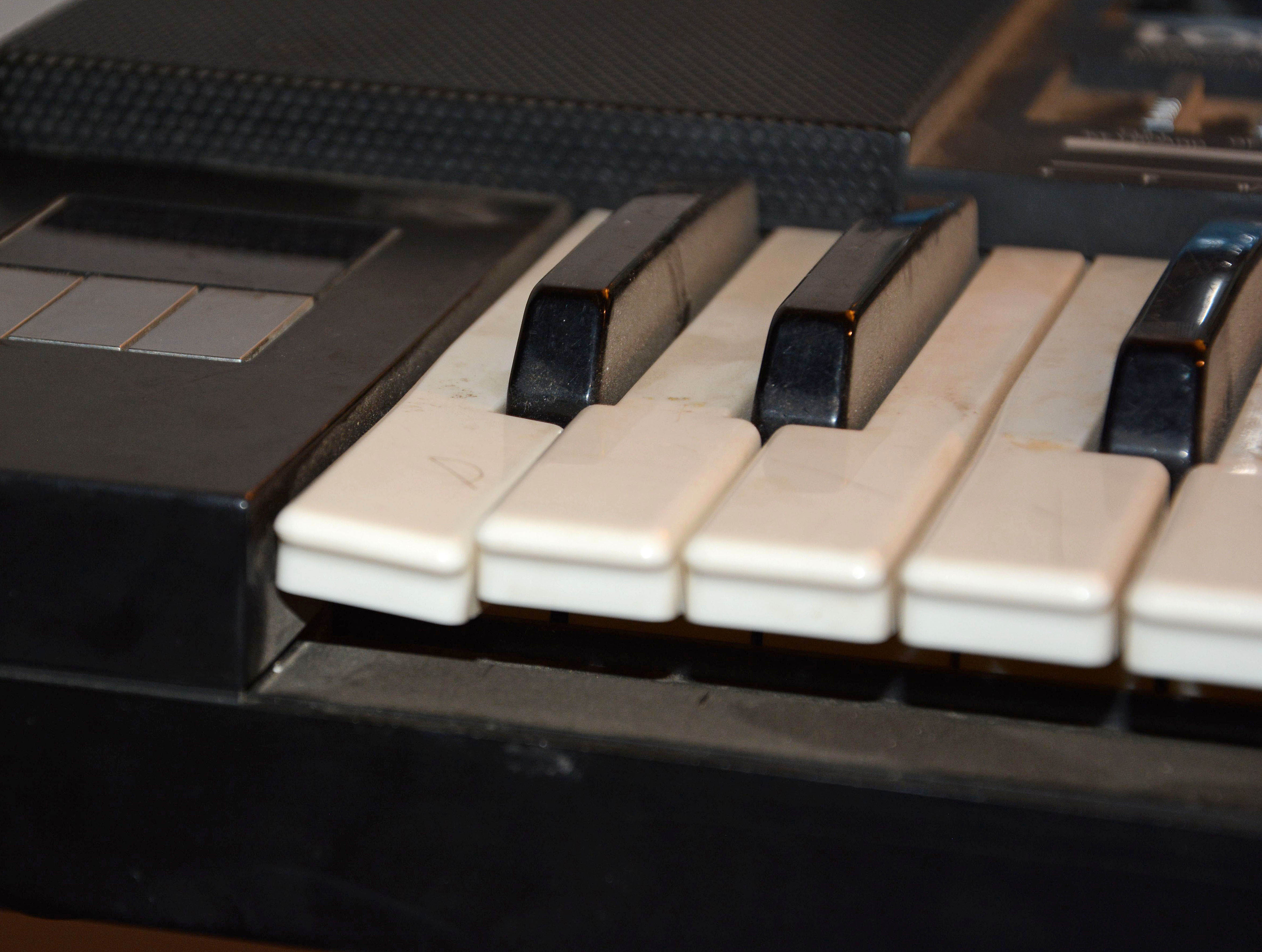
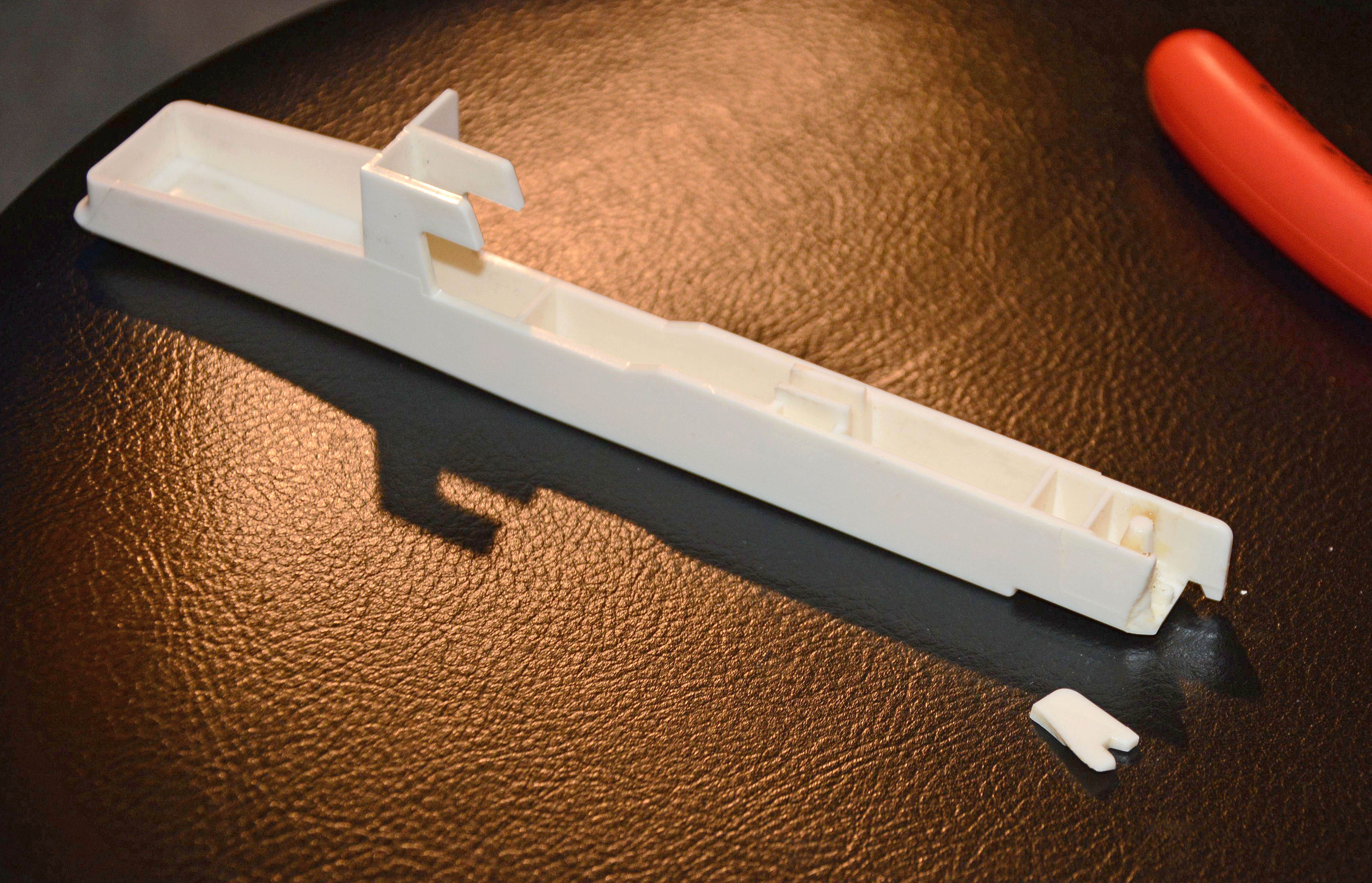
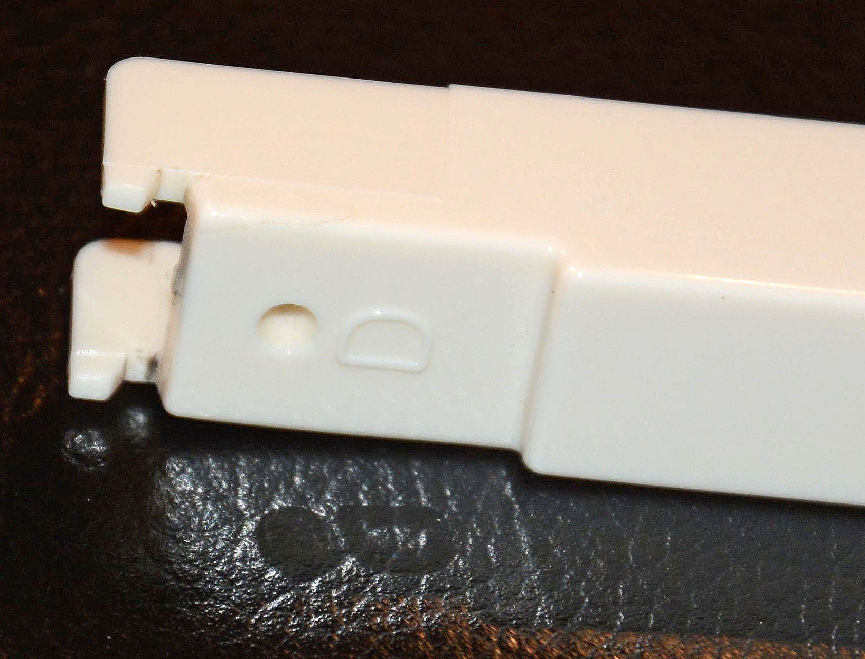
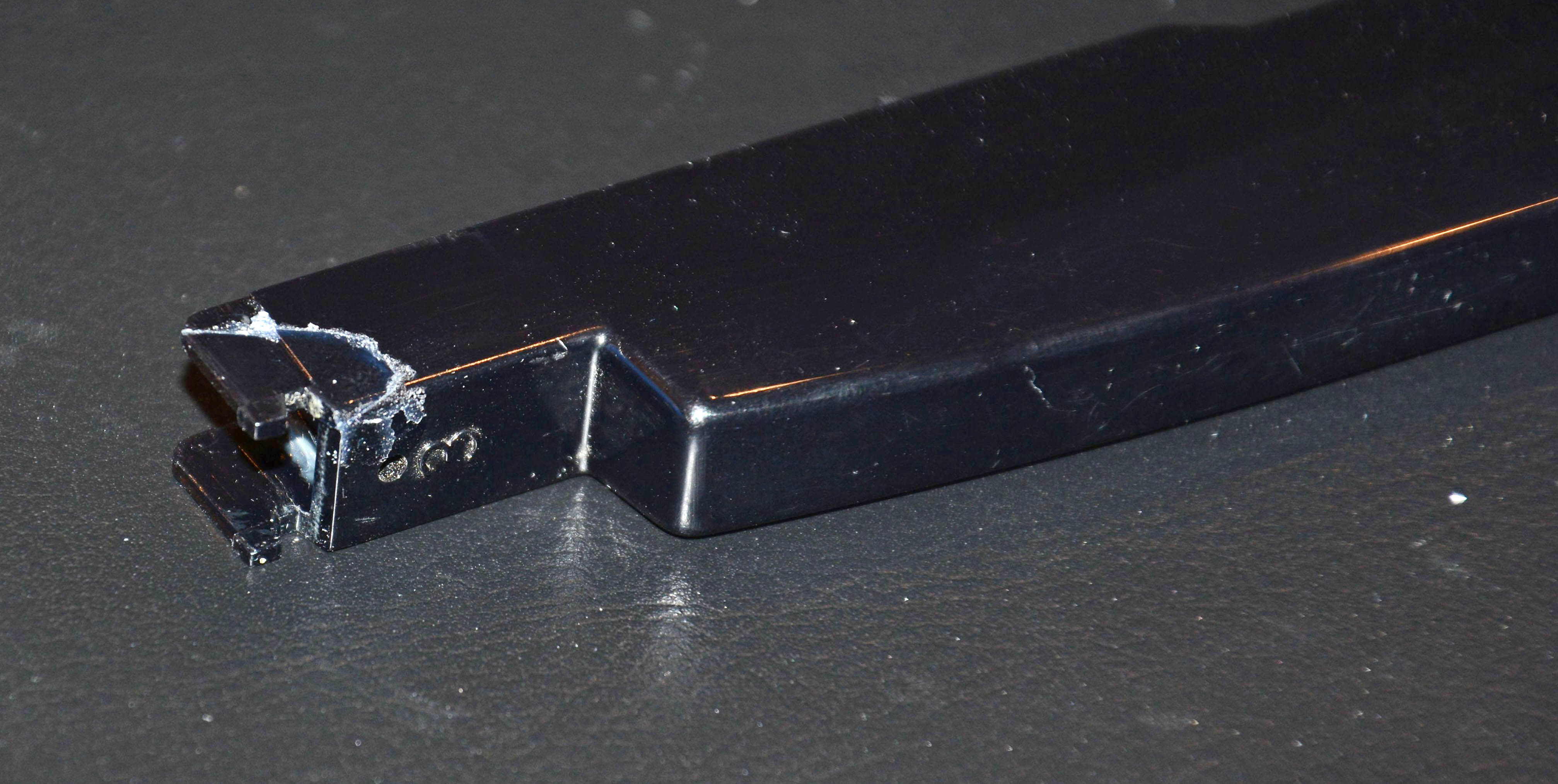
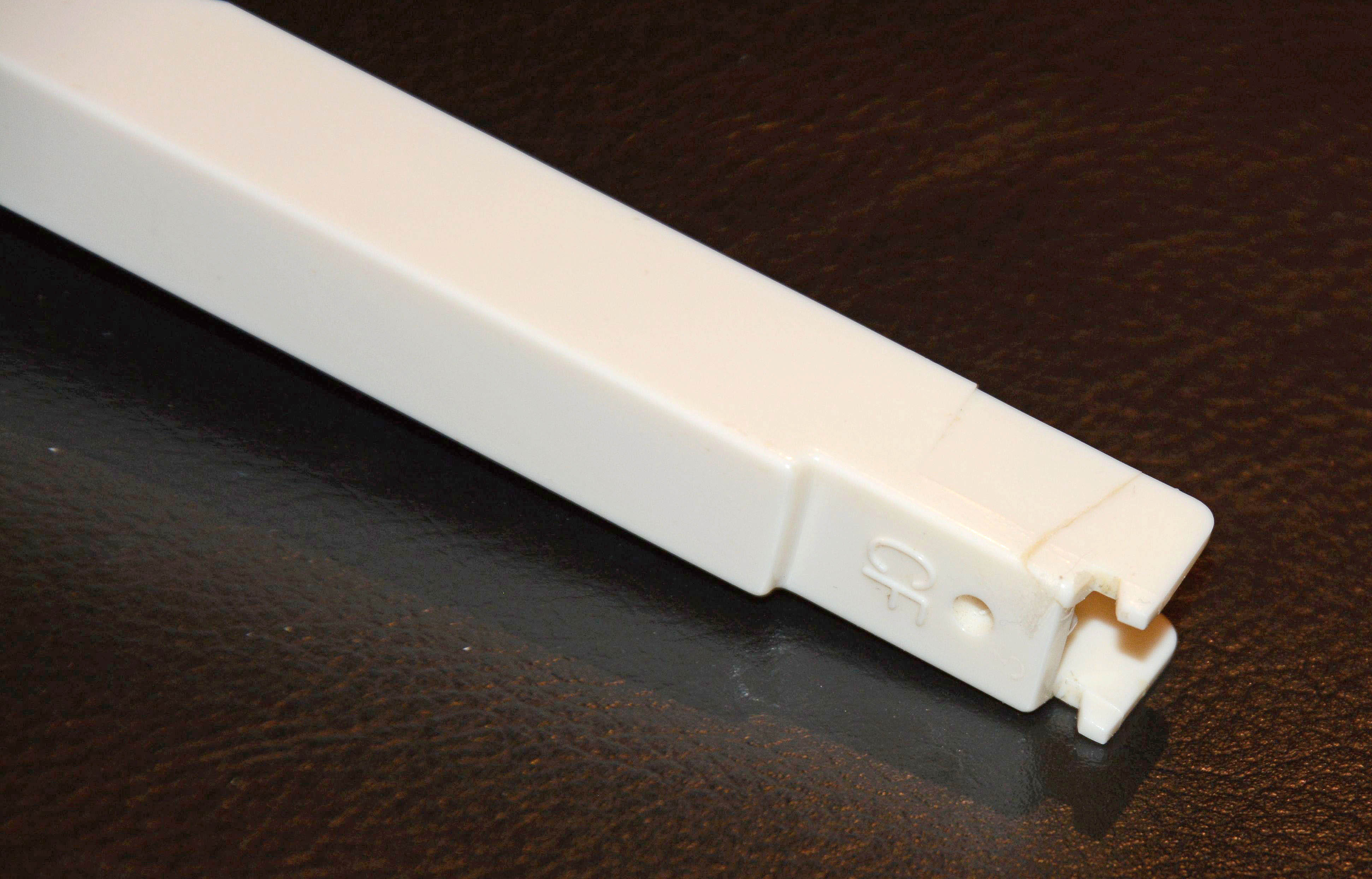
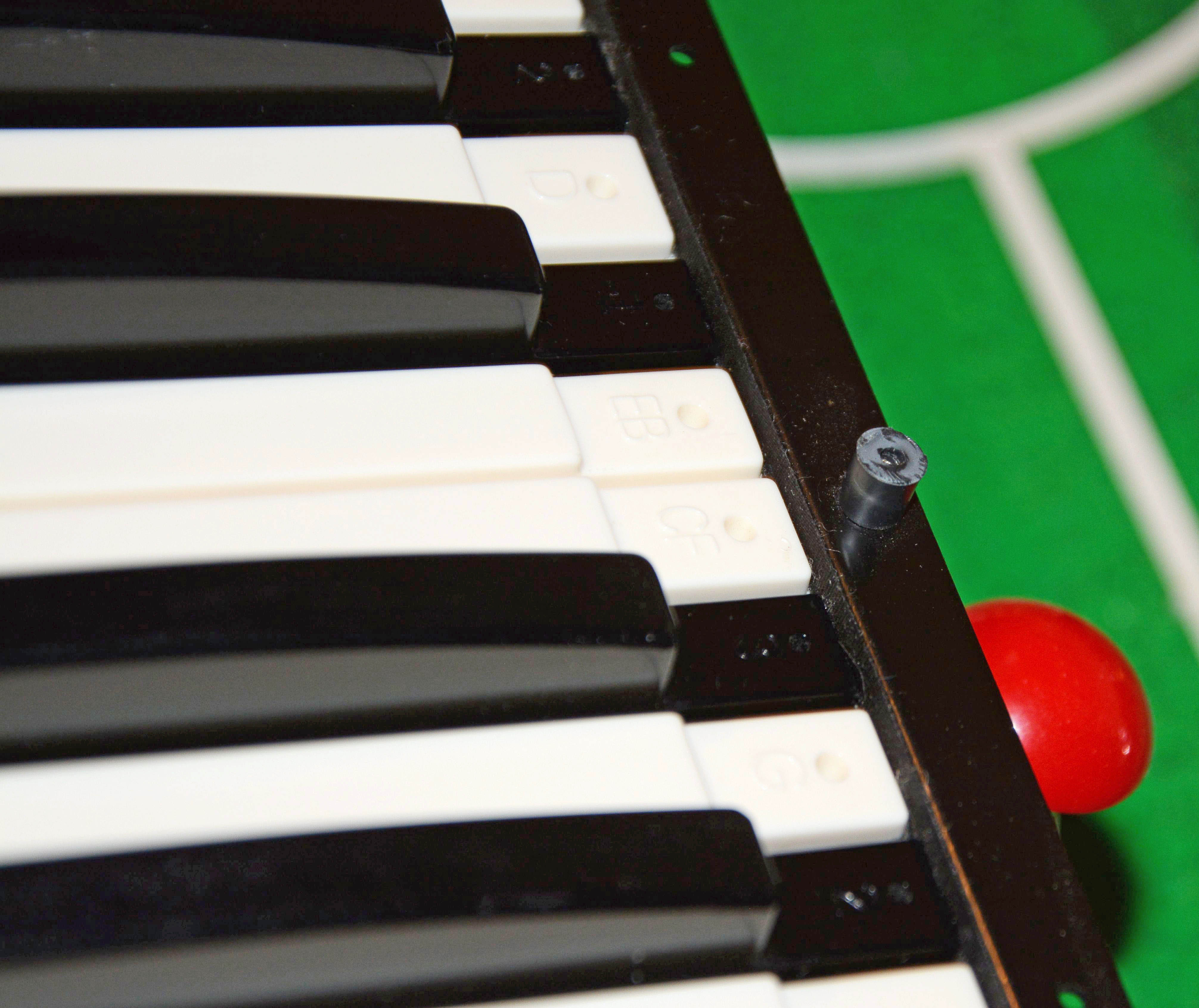
I also cleaned all of the pushbutton switches, first with Contact Cleaner with Silicone (in 2015), and again with Electrosolve (in late 2018), and at least twice in 2019. While this cleaning helped in the short term, it never lasted. The switches returned to being intermittent, especially the preset switches, probably indicating physical wear besides dirtiness, and thus a poor design. I have not found suitable replacements. Lowrey gives the part number of the effect & preset switch assembly as 460-034836-000 in the SM, which gives no useful search results. Not surprising. As for the two sideways keys, broken plastic at the pivot points was the cause. Thankfully, the snapped-off chunks were still inside the body! Another key—the D directly beside the broken D#—was just starting to crack at the same point, so this was also repaired in the same way. In order to remove the keys, the entire keyboard assembly had to be removed from the rest of the case. I was able to figure it out on my own, but there are instructions in the service manual if you have difficulty. Here are the C and D keys prior to repair:
A little bit of thin cyanoacrylate glue did the trick.
Having the keyboard disassembled made for a good opportunity to clean the filthy keys and keybed.
Another plastic repair was this broken mounting post, one of four attaching the back of the metal keyboard frame to the top plastic piece. This was also repaired with cyanoacrylate glue once the keyboard assembly had been reattached to the top section. I am really not a fan of plastic as a body material, especially when the design is so blatantly inadequate—the heavy metal-frame keyboard assembly is held by only four thin and brittle posts!
At this point, the instrument was completely functional, but...
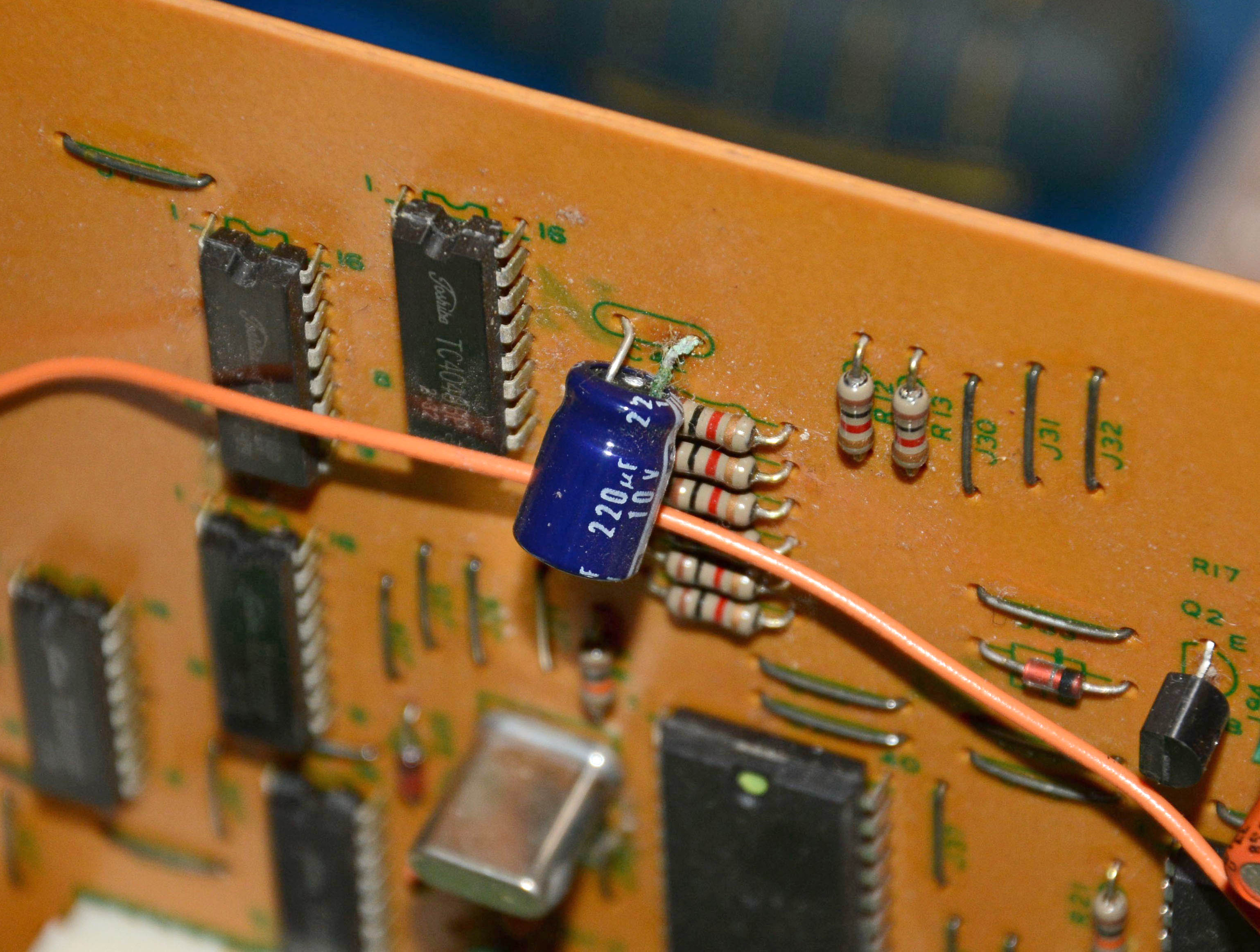
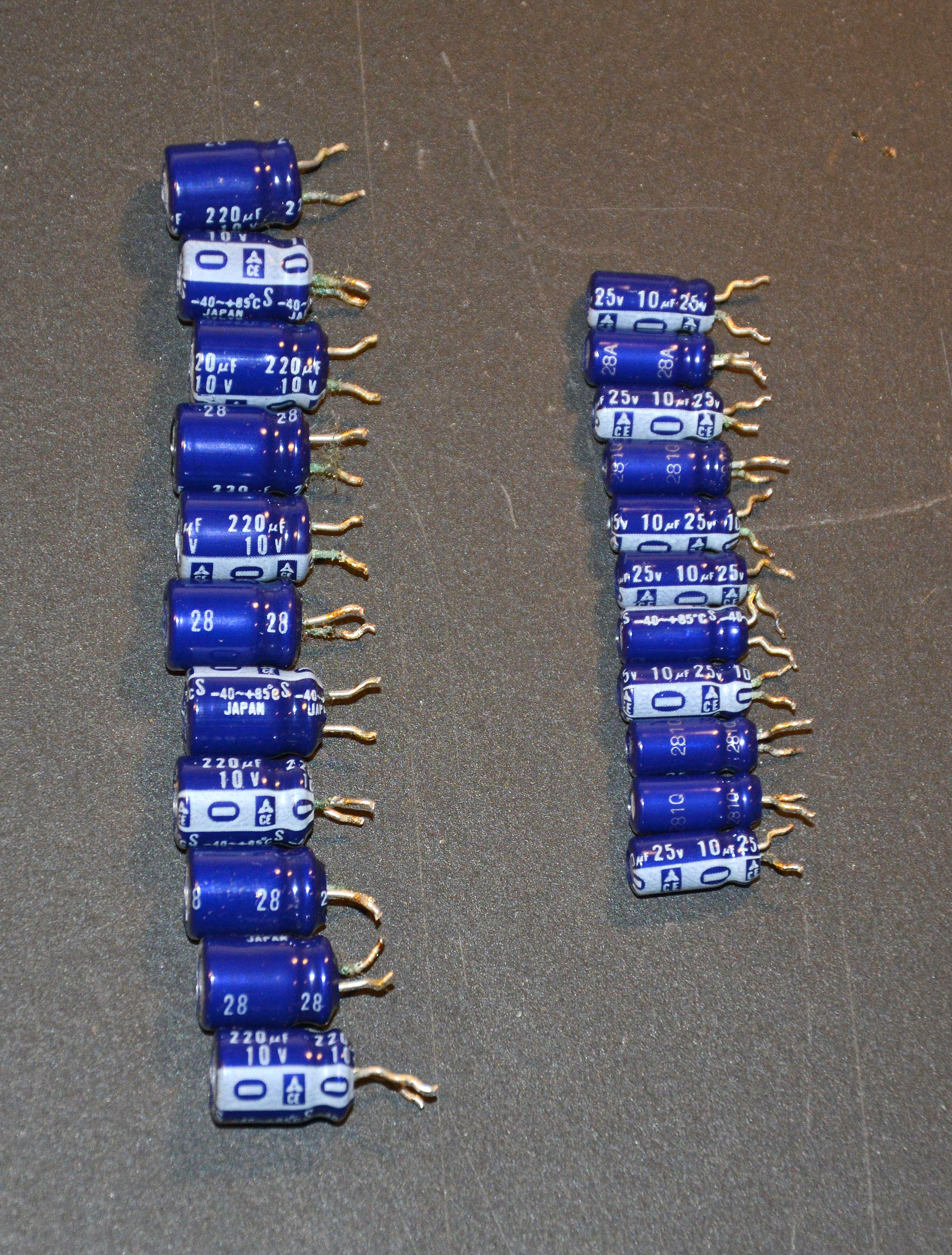
Every 220µF 10V and 10µF 25V electrolytic capacitor had corrosion on one or both leads, due to leakage of the electrolyte. The others of the same series but different values (such as 1µF, 100µF, and 470µF) were all fine. I have seen this many times in other '70s and '80s Japanese electronics using Matsushita CE capacitors—I often find them bad, but always just certain values. They are a notorious type, and if left longer, the electrolyte would've dissolved solder joints and PCB pads, causing functional issues. I decided to replace all of the leaky types, which was straightforward; eleven 10µF and eleven 220µF capacitors were replaced, as shown below.
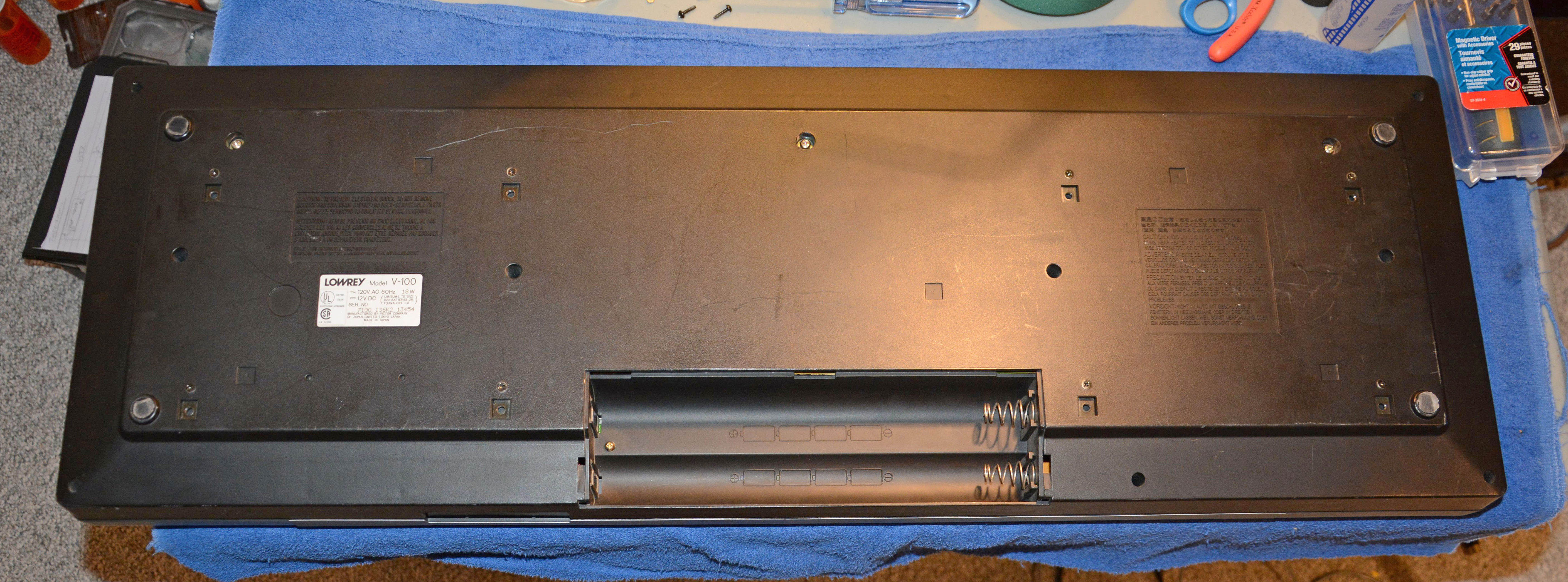
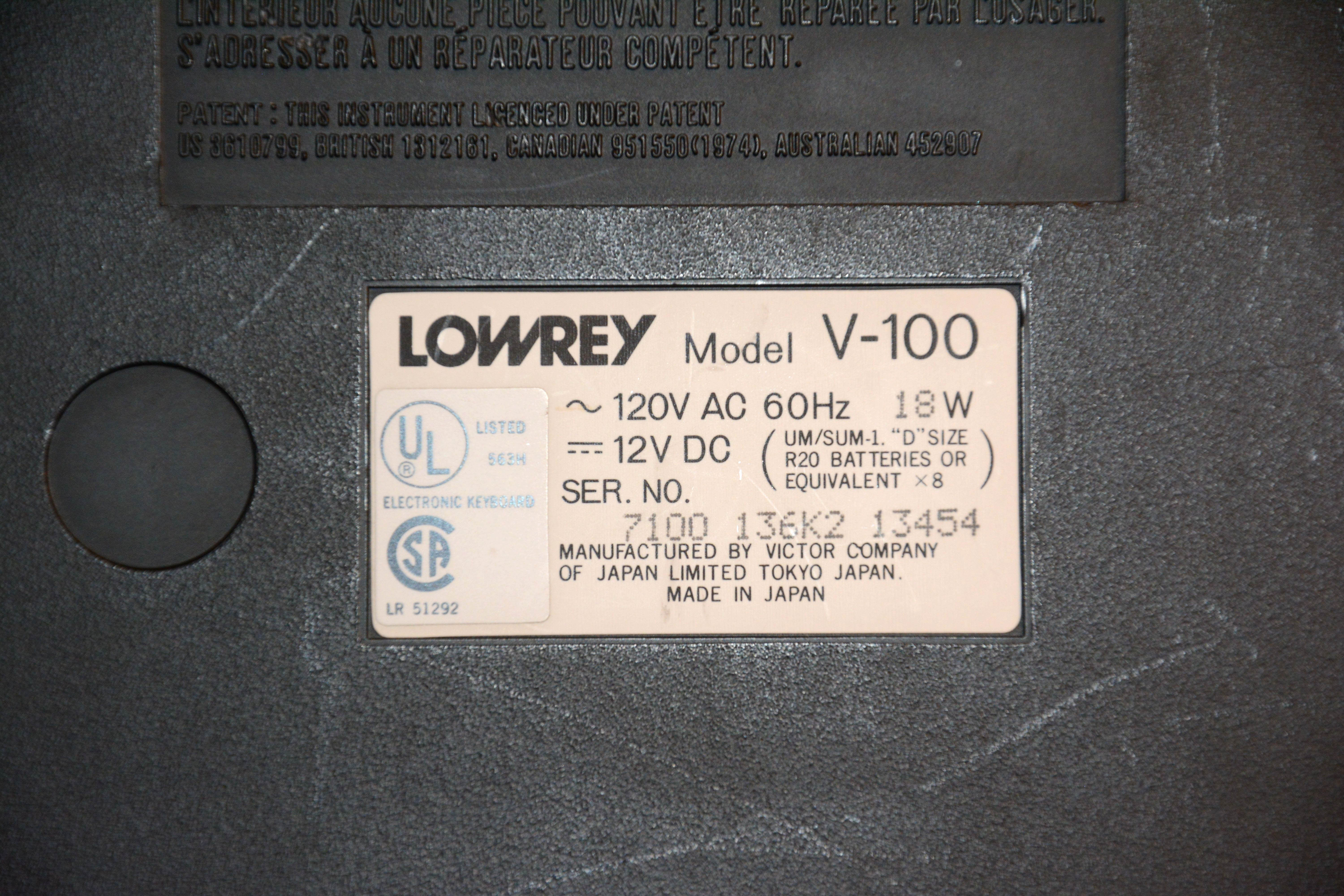
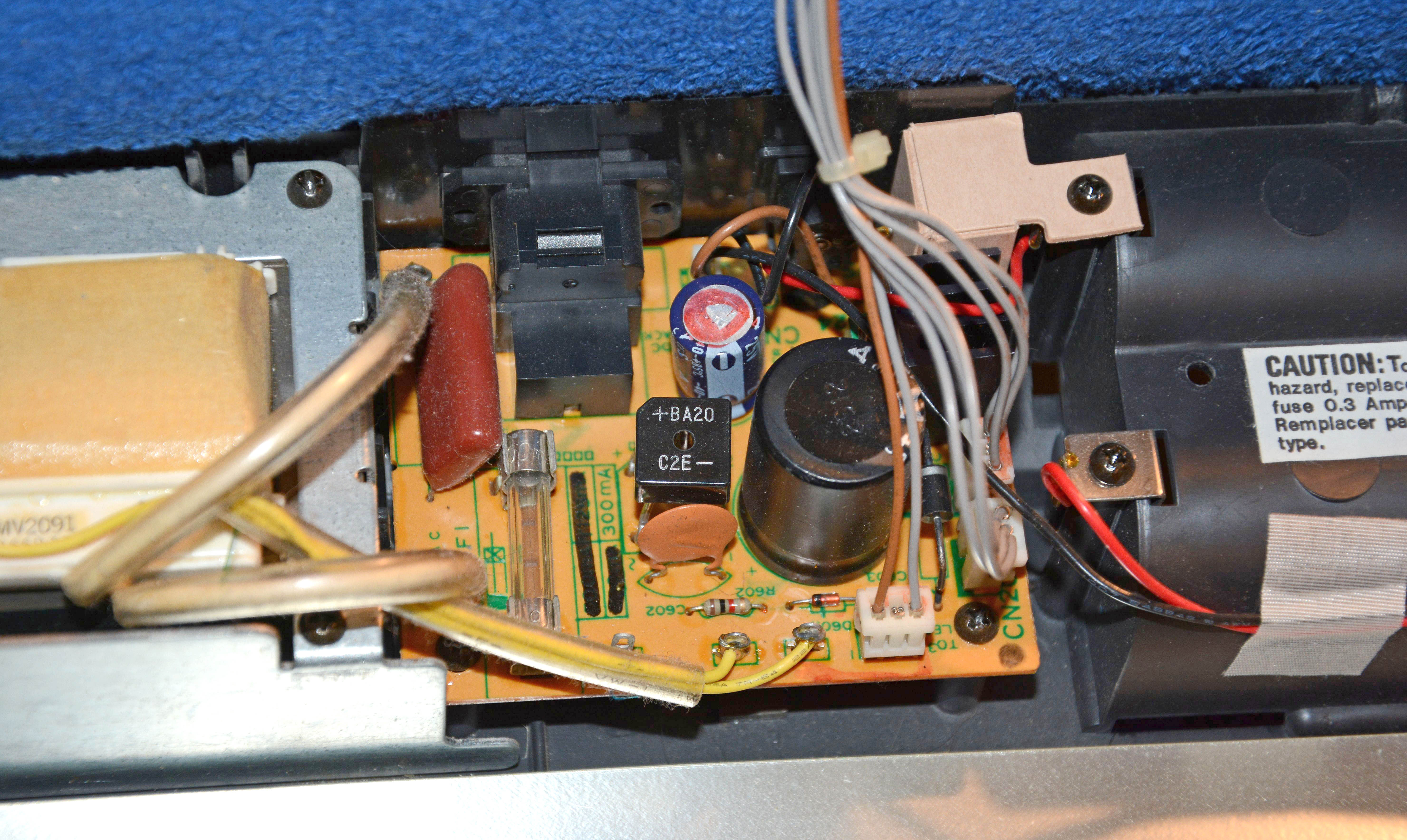
One final note, and that is that initially, I thought the Mach III sequencing/"recording" feature was not working, since I could not get any of the LEDs to respond no matter what I pressed. Only after I received a copy of the service manual did I figure out how this works. Page 8 indicates that the instrument must be in Music Chord mode and with the Auto Start switch pressed, with the rhythm running, and then you can press the Record button, making the record light and one of the channel lights turn on, select the channel, and then play the chord progression and have it recorded. Unbelievably unintuitive! The HardwareLet's start with the bottom, on which there is not much to see. First, notice the eight threaded metal inserts for mounting the long-gone original stand. Then notice the battery compartment, the cover of which is also long gone. It takes eight D cells, which the service manual states will last only 3 hours at full volume! Note as well that Lowrey made no attempt to hide JVC as the true manufacturer—it is printed right on the label.
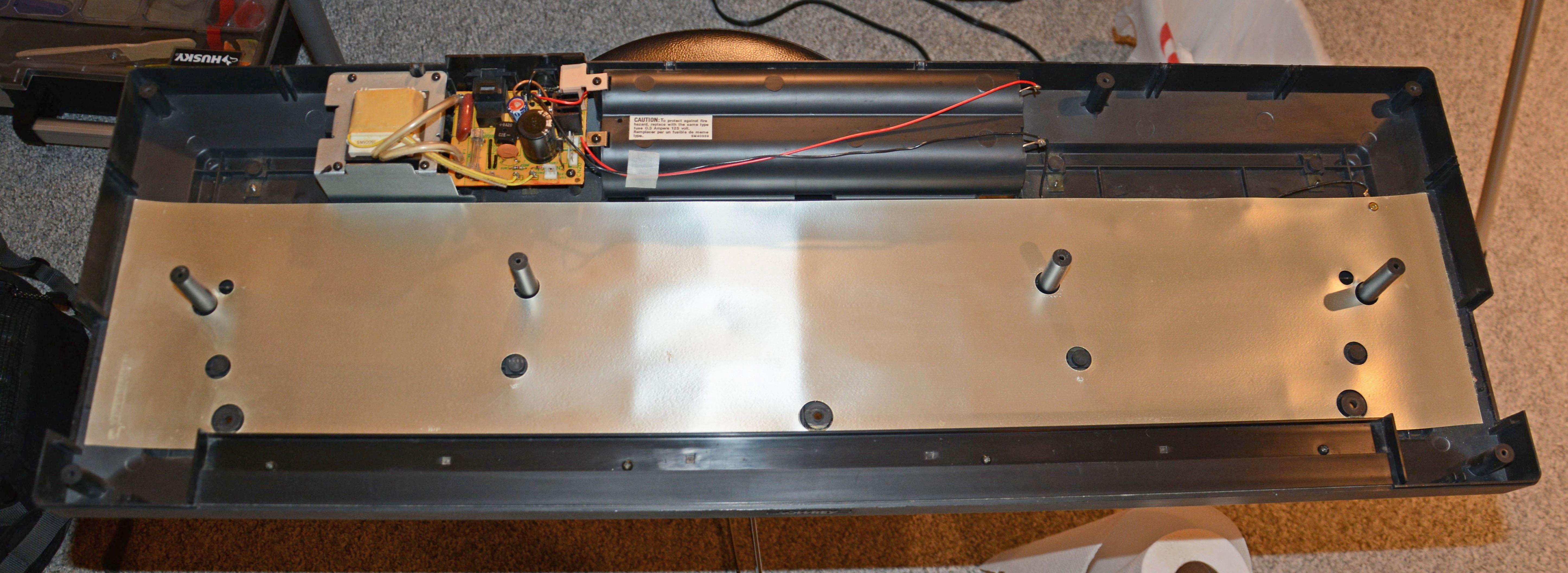
Opening it up can be done by the removal of 13 screws on the bottom, instructions for which are in the service manual. The top and bottom halves are then joined only by three cables towards the back, which connect the "Rectifier" board in the bottom to the "Regulator" board in the top. Unless you have a large workspace where the bottom piece will not get in the way, it's best to disconnect these when power is not necessary. Conveniently, there are hand-written numbers on the plugs that match the socket references. The bottom half doesn't have much mounted to it besides the power supply circuitry and a foil-coated-cardboard shield:
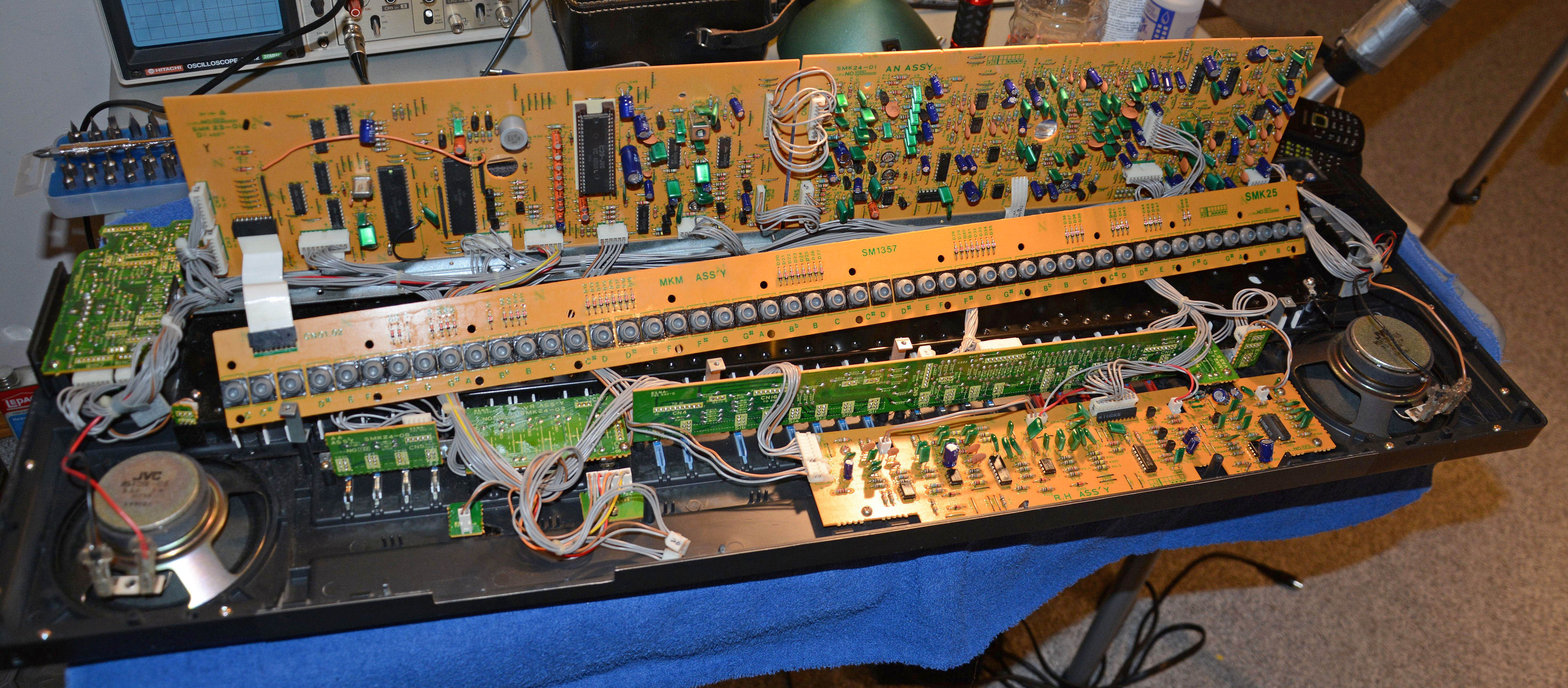
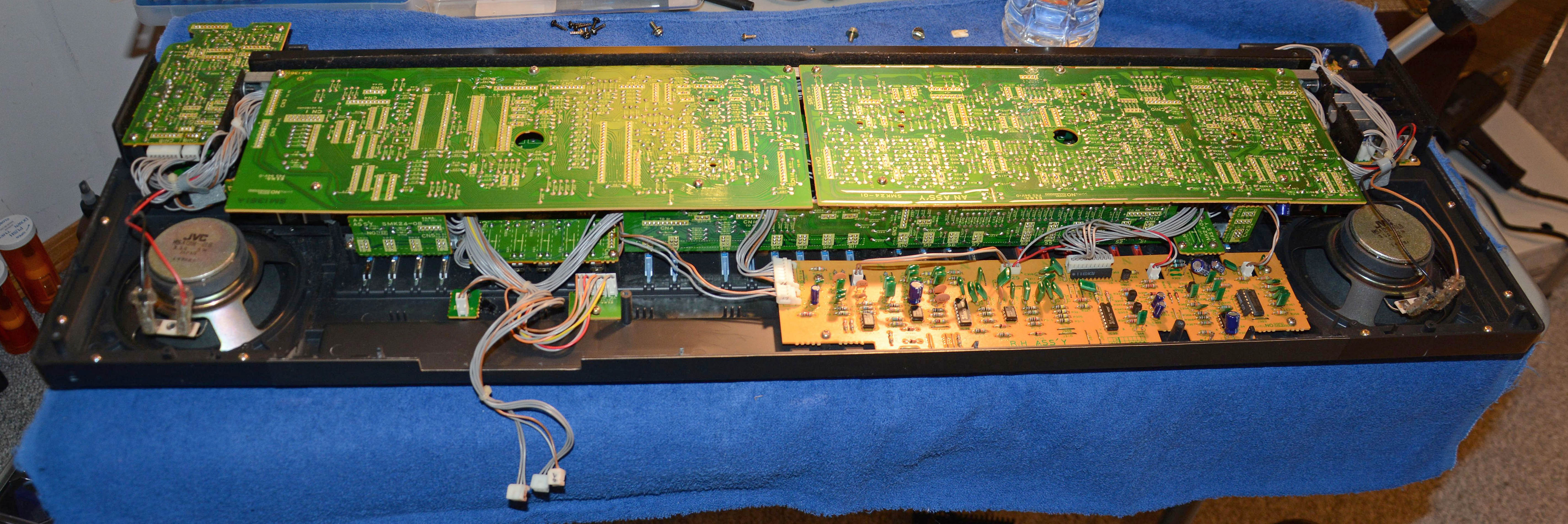
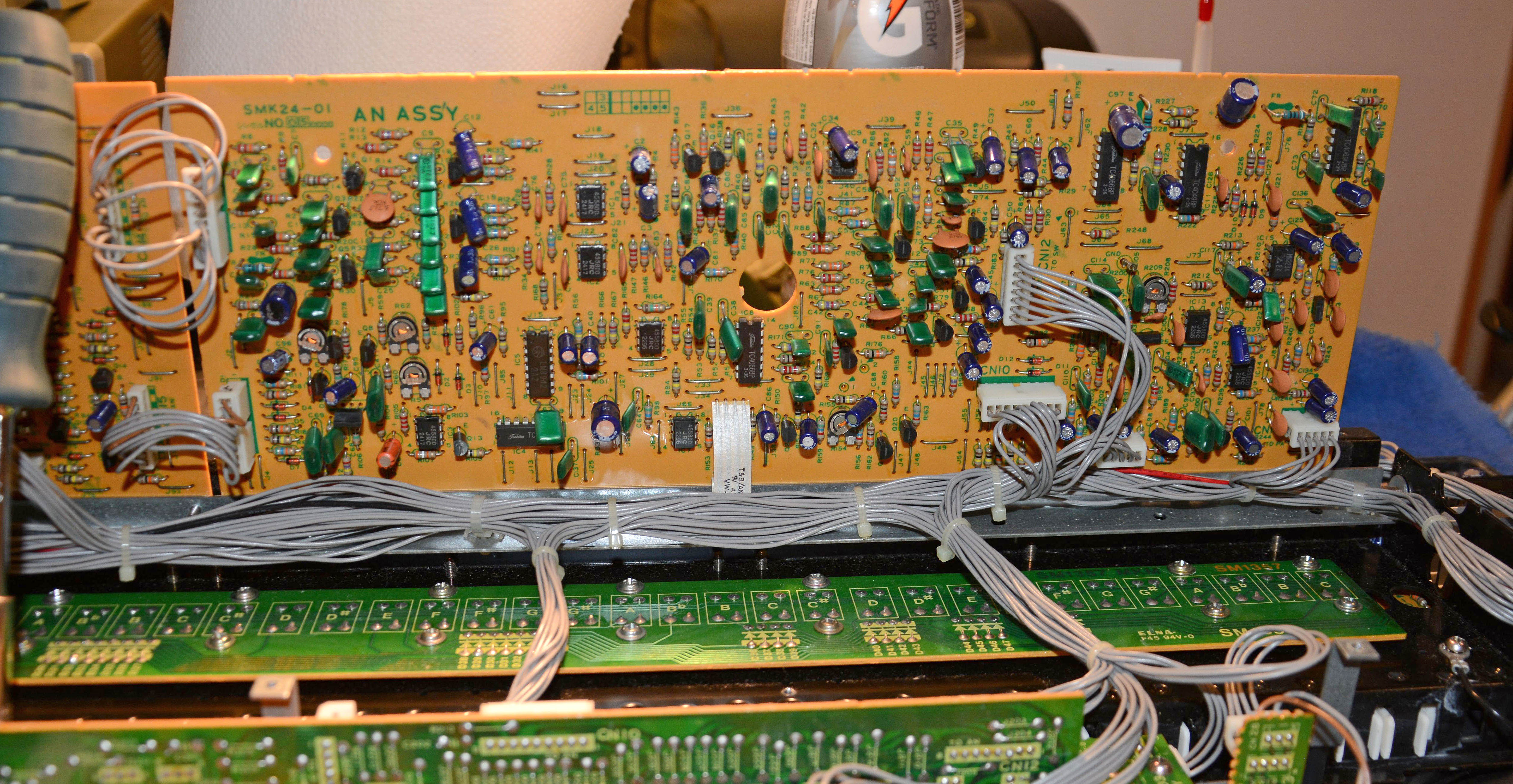
Everything else is mounted to the top half. Unlike the largely hollow keyboards of today, this unit has almost every bit of free space filled. It containts a remarkable amount of electronics for its size, with 13 circuit boards in total. The two largest and most obvious boards are called the "Central Processing System" and "Quality Control" boards by the service manual; on the actual boards, they are marked as the "D1 Ass'y" and "AN Ass'y" respectively. These are mounted on a metal bracket on a hinge, which can be moved upwards 90 degrees into servicing position after the removal of four screws.
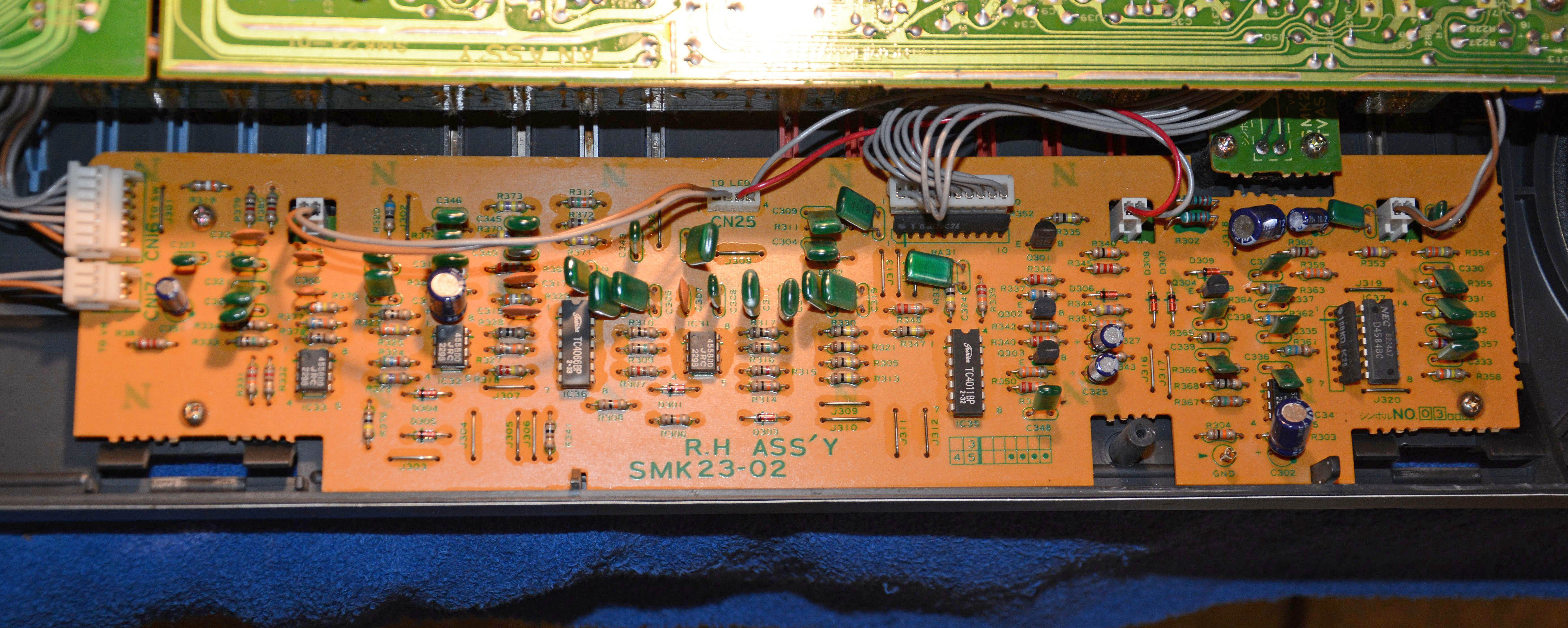
Another large and obvious board is mounted directly on the top case towards the back. This is Board 3, the "Rhythm Instrumentation" or "RH Ass'y" board.
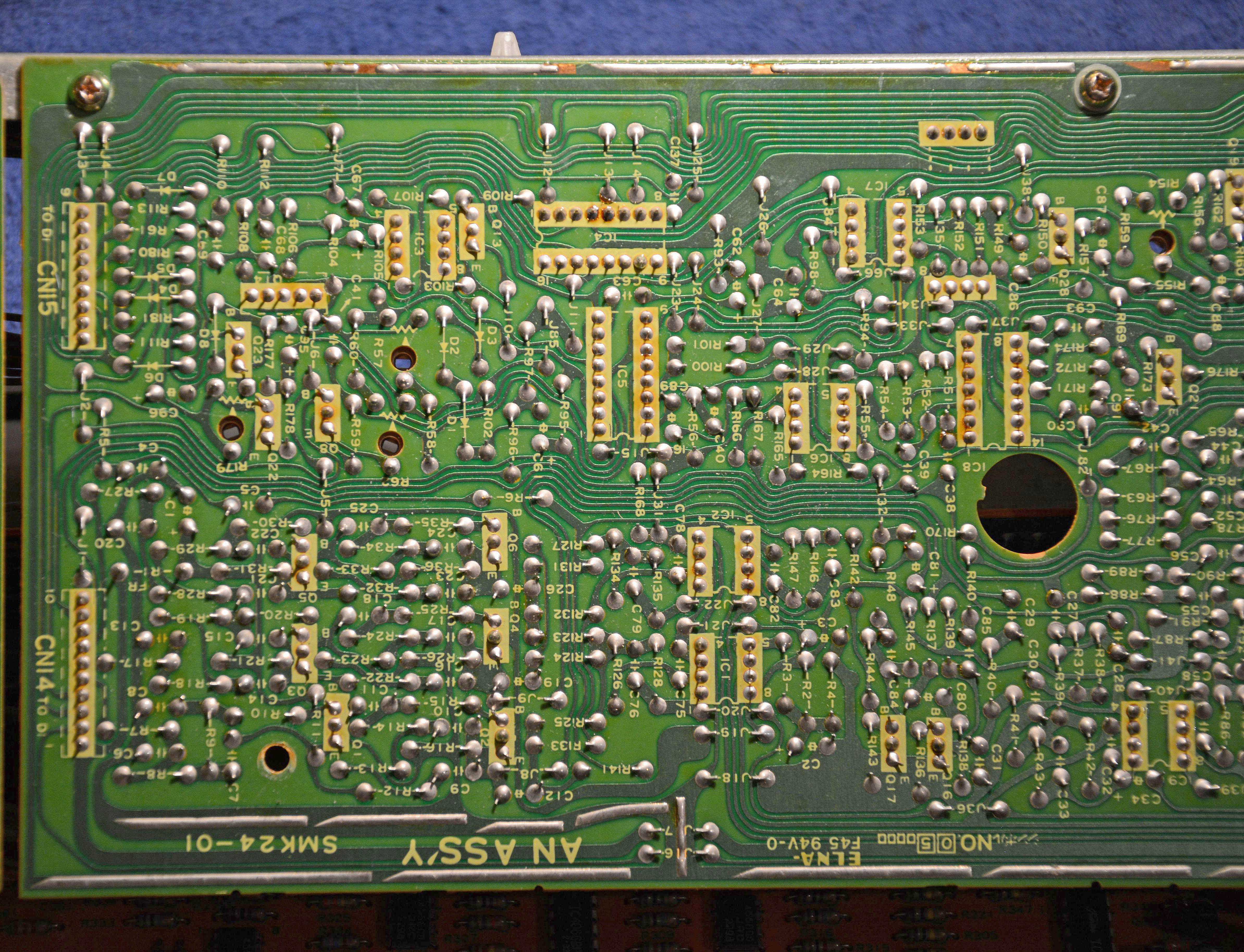
As for electronics, the V-100 uses an interesting mix of analog and digital circuitry, again reminding us that we are in the highly transitional '80s. Virtually all functions capable of being implemented with ICs are done with such. There are three LSI chips, which are a microcontroller (MCU), RAM & I/O chip, and a custom JVC tone generator chip. The rest are mostly 4000 series CMOS logic and various linears (4558 dual op-amp, MN3204 bucket-brigade device, LA4125T power amp, etc.) typical of early '80s designs. All components are through-hole, with all boards being single-sided and made of phenolic paper. Before continuing, let's have a look at the block diagram, as presented on page 18 in the service manual:
The MCU chip is an OKI MSM80C49-21RS, which is a CMOS version of the Intel 8049 with 2048 bytes of mask ROM and 128 bytes of RAM. This is supported by an OKI MSM81C55RS (i.e. 81C55), which contains 256 bytes of RAM as well as some I/O circuitry. These do much less than the computer systems in modern digital keyboards, which typically are responsible for the entirety of tone generation through DSP software and prerecorded samples. Rather, in this case, these chips are used for interpreting the keyboard input and some switch settings, triggering the rhythm generating circuits and beat LEDs, providing the Mach III sequencer functionality, and controlling the tone generator chip.
Speaking of which, all sounds except rhythm and the noise in the flute voice are generated by the 42-pin "Programmable Tone Synthesizer" chip: the JVC VC4050BL shown below, or VC4050BH as specified in the SM. It is the only socketed chip. It has a basic description on page 12 of the SM, but this is not complete and has some errors and confusing aspects, so I will try to give a better explanation. To start with, the chip contains ten programmable frequency dividers, which divide the 1MHz master oscillator (generated externally) down into the desired pitches, controlled digitally by the MCU. One divider is always allocated to the bass, and another to the arpeggio. The remaining eight are split between the accompaniment chords and the preset voice. In "full keyboard" mode, all eight go to the preset notes. In "genie" mode, four go to the chord notes, and four to the preset notes. In "music chord" mode, only three go to chord notes, while five go to preset notes. The signals from these eight dividers, which I will call the "main" dividers, are further divided to give four octaves aka "footages" of squarewaves: 2', 4', 8', and 16'.
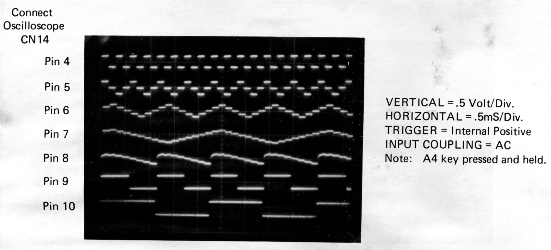
This is where things become uncertain, due to the incomplete description and lack of other information on the chip; however, after some thought, I believe I've figured out how it works. From here, the divided squarewaves are probably added in appropriate proportions or applied to simple digital logic circuits and digital-to-analog converters to form stepped approximations of triangle waves (in 4', 8', and 16' footages) and sawtooth waves (in 8' and 16' footages) to serve as basic tones from which the preset voices are formed. Stepped sawtooth waves can be produced simply by adding octavely related squarewaves, a technique called staircasing for which a good description can be found in Richard Dorf's Electronic Musical Instruments, 3rd Edition. Oscillographs of the waveforms are shown on page 40 of the SM and reproduced below. Note that the steps are as long as a half-cycle of the 2' squarewave, as expected from the design described. Similar techniques are most likely used to generate the chord (8' sawtooth, not triangle as stated on p. 12), arpeggio (4' square, not 8' as stated on p. 21), and bass (8' pulse) waveforms. Note that as also shown on page 40, the bass waveform is a pulsewave of roughly 80% duty cycle rather than a plain squarewave, to avoid hollowness caused by lack of even harmonics.
Then, these analog signals are fed to amplifiers with controllable gain. To be specific, there are nine signals derived from each of the eight "main" dividers (2', 4', 8', and 16' squarewaves; 8' and 16' sawtooths; and 4', 8', and 16' triangles), one signal (4' square) from the arpeggio divider, and two signals (8' and 16' pulse) from the bass divider. As well, one signal (8' sawtooth) is present for each of the four chord notes, but these are probably just from the "main" dividers' 8' sawtooths, simply switched over to the "chord" signal path. While I don't know the exact arrangment of amplifiers, I'm guessing that there must be one amplifier for each signal of each preset note, giving 9 × 8 = 72 amplifiers; this is the only way I can think of to have both independent footage+waveform outputs and separate envelopes for the eight preset notes. The chords may have a separate amp, or just use the preset note amps, and then there is probably an amplifier each for the arpeggio and bass. These amplifiers are controlled by envelope generators, 11 in total, with external capacitors and control voltages that determine how they behave. The bass, arpeggio, and chords each have one envelope generator, and the remaining eight are for the eight preset notes. There are three important control lines: the "percussion sustain enable" line, the "percussion snub control" line, and the "sustain" line. The percussion sustain enable line enables or disables the envelope decay— it is enabled only on the Piano, Hawaiian Guitar, Harpsichord, and Vibraphone voices, as expected (see page 22). Interestingly, this is controlled digitally by the MCU, as there is no analog control voltage (CV) input; rather, the "percussion snub control" line does have a CV input, and is enabled on the Piano and Harpsichord voices, causing a faster envelope decay. Lastly, the "sustain" line goes to a CV input on the chip, and has short, medium, and long states depending on the selected preset and the sustain button. Finally, the signals from the amplifiers are summed to their respective footage outputs (e.g. all eight 2' squarewave outputs get summed to pin 42), and go on to be filtered and otherwise processed by external analog circuitry. This ends my description of the tone generator chip—if you have any comments (an especially if you have any datasheet or other info on the chip), please let me know. I emailed JVC to see if they have anything, and they responded in the negative. The rest of the circuits have good descriptions (or at least the schematics are easy to read) in the SM, so I won't try to explain them here. Check out the vibrato circuits if you get a chance. As well, the rhythm sounds are generated completely seperately from the tone generator chip, with circuits using discrete transistors and op-amp ICs as the active components. This is done on the "RH Ass'y" board shown previously. I should also point out that while the MSM81C55RS (or equivalent) is still relatively easy to source (being a common non-programmable RAM and I/O chip), the MSM80C49-21RS and VC4050BL chips are virtually impossible to find except inside these instruments, which themselves are now rare. This is because these two chips are custom devices with low production; the MCU might only have been used in this exact model, while the synthesizer chip was probably used only in a few models of JVC keyboards. Even if you source another variant of the 8049 MCU, it will be useless, since it won't have the correct mask ROM. [see insertion below] And JVC's custom tone generator chip is so obscure, I can find absolutely nothing online—no datasheet, and none for sale. Thus, like in all cases where low-volume and programmable ICs are used, the repairability of this instrument is severely limited in the event that either of these chips fail. This is why I prefer discrete designs, or those that use only common non-programmable ICs. Also, going back to the mask ROM of the MCU, considering that it determines how the chord fingerings work, it would be interesting to know if the KB-500's MCU is truly a different type. With the help of T-150, I received this interesting information from C. O. Windler of Tablehooters fame. He owns the more advanced JVC KB-700, and provides some info about it, and his sadly unsuccessful efforts trying to dump the ROM of the 8049 CPU. Most importantly, he points out that an 8749 processor (ideally a CMOS version, which I'm not sure exists) should be a drop-in replacement of the 80C49 if programmed with the correctly-dumped ROM data. In his words:
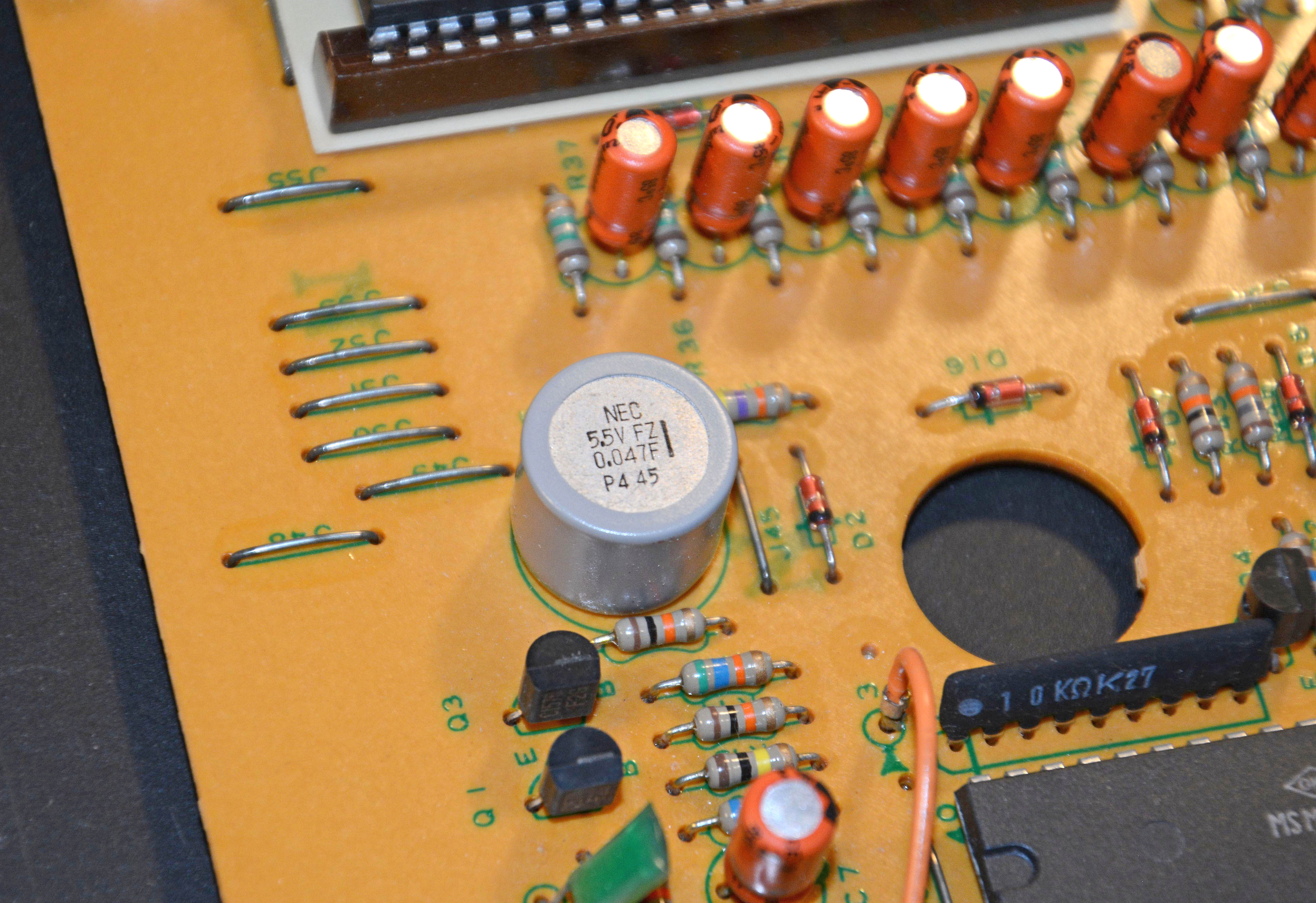
So, the challenge is figuring out how test mode works, since the OKI chip apparently does not go into test mode like a real Intel chip. I bet it has a test mode (for checking the mask ROM during manufacture), but more info is needed. Also, I've added a link to the JVC KB-700 service manual (also thanks to T-150 for finding this), for comparison to the KB-500 / Lowrey V-100. The text descriptions are less detailed than Lowrey's manual, but it still gives full schematics and other useful diagrams and parts lists. One last interesting thing to note: near the tone synthesizer chip is a 0.047F (i.e. 47,000µF) capacitor that is used to retain the contents of RAM for "up to fourteen days with the organ power turned off," according to the SM. This is the earliest example I've found of a supercapacitor used for memory backup, especially given that mass production of supercapacitors began around 1978.
The SoundsLike many keyboards of the 80s and beyond, the V-100 has a large variety of sounds it can produce. It would take a lot of text to describe all of them, and it would be ambiguous no matter what, so I will skip the description this time. There are already some videos and sound samples of the keyboard online, including on the KB-500 page of the website dedicated to JVC keyboards, a link to which is in the section below. Downloads & Links
|
| If you notice any errors or have additional information that you would like to add, please contact me! |


First Published: 01/06/2019